Featured Product Archive
The inventions and products featured on these pages were chosen either for their
uniqueness in the RF engineering realm, or are simply awesome (or ridiculous) enough
to warrant an appearance.
| 1 |
2 |
3 |
4 |
5 |
6 |
7 |
8 |
9 |
10 |
11 |
12 |
13 |
14 |
15 |
16 |
17 |
18 |
19 |
20 |
21 |
<Previous
Next>
As you might know if you have been
visiting the RF Cafe website for a while, my specialty while in the U.S. Air
Force was an Air Traffic Control Radar Repairman
(AFSC 303x1). Technical school at Keesler Air Force Base in Biloxi, Mississippi,
included training on the USAF's primary fixed and mobile radar systems at the time
(late 1970s). After graduation, I was assigned to the 5th Combat Communications
Group at Robins AFB, Georgia. There, I worked on AN/MPN-14 mobile radar system (2
to 3, depending on how many we happened to have at the time). The AN/MPN-14 was
essentially a modified AN/MPN-13 (utility and
operations trailers) with the addition of a large mobile RAPCON trailer. I have
attempted over the years to get hold of the schematics and troubleshooting and alignment
technical orders (TOs), but with no luck. If you happen to have copies of any of
them, please let me know and I will pay to have them mailed to me for scanning,
then returned to you.
One technical reference I found online to the AN/MPN-13 and AN/MPN-14 is this
"MIL-HDBK-162A
Military Standardizations, Radar Equipment, 1965."
AN/MPN-13 Landing Control Central
 Date 1 October
1964 Date 1 October
1964
Item Name: Landing Control Central
Cognizant Service: USAF
Type:
AN/MPN-13
Federal Stock Number (FSN): 5895-885-2274-EG
Mfg(s) Name or Code
Number: Gilfillan Corporation
Functional Description
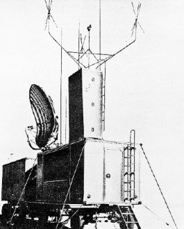
Landing Control Set AN/MPN-13 is a self-contained mobile, ground-controlled-approach
(GCA) radar equipment, used as an air-traffic control center for precision landing
of aircraft during periods of reduced visibility. The AN/MPN-13 consists of a search
radar set used for initially locating aircraft flying within a 30-mile radius of
the set, a precision radar equipment preset to track aircraft down a specific glide
path during the final approach, and radio communications equipment to provide essential
two-way communication between the ground and the aircraft. Landing Control Set AN/MPN-13
is an improved model of the AN/CPN-4 models and AN/PPNI1A, AN/MPN-11B, and AN/MPN-11C
incorporating recent changes such as extended range coverage, additional search
cursors, improved receiver design, and monitoring of the power output, relative
tuning, and noise figure characteristics. The AN/FPN-13 has all the modes applicable
to the AN/CPN-4 and AN/MPN-11 applied to it.
Relation to Similar Equipment
The AN/MPN-13 is similar to the AN/MPN-14 without the mobile RAPCON added. The
AN/MPN-13 is either a basic AN/CPN-4, AN/CPN-4A, AN/CPN-4B, AN/MPN-11A, AN/MPN-11B
or an AN/MPN-11C, difference is an improved model incorporating recent changes.
The AN/MPN-13 is similar to the AN/MPN-15, difference is in production models.
Technical Description
Search System
- Frequency Range: 2780 to 2820 *c
- Power Output: 600 kw (peak)
- Pulse Repetition Rate: 1500 pps
- Range: 20 to 30 mi, depending on type of aircraft tracked.
Coverage
- Azimuth: 360 deg
- Elevation: 1/2 to 45 deg
System Accuracy
- Azimuth: 1 deg
- Range: 4 pct
Resolution
- Azimuth: 3.3 deg
- Range: 500 ft
Precision System
- Frequency Range: 9000 to 9160 mc
- Power Output: 45 kw (peak)
- Pulse Repetition Frequency: 5500 pps (1800 pps on indicator)
- Range: 10 mi
- Coverage
- Azimuth: 20 deg
- Elevation: 7 deg
- System Accuracy
- Azimuth: 0.6 pct of range
- Elevation: 0.3 pct of range
- Range: 2.0 pct
- Resolution
- Azimuth: 1.1 deg
- Elevation: 0.6 deg
- Range: 200 ft
- Communication System: hf, vhf and uhf radio sets
- Air Conditioning System
- Temperature Range (Dynamic): -54 deg C (-65 deg F)
to 49 deg C (120 deg F)
- Power Requirements: 120 or 208v, ac, 50 cps, 3 ph,
4-wire, 25 kva.
Installation Considerations
- Siting: Clear, level area adjacent to aircraft runway, removed from any blocking
or obstructing structure.
- Mounting: Cargo trailers are used to mount equipment.
Principal Components and Physical Data
Antenna Support (vhf) AB-194/GPN
Antenna Base AB-195/GPN
Antenna Support (uhf) AB-333/GPN
Radar Test Set AN/GPN-16
Antenna Horn AS-513/GPN
Antenna (Azimuth) AS-519/GPN
Antenna (Elevation) AS-520/GPN
Antenna (uhf)
AT-197/GR
Antenna AT-282/GPN
Antenna AT-283/GPN
Antenna Reflector (Search)
AT-284/GPN
Antenna AT-285/GPN
Antenna Reflector (Azimuth) AT-290/GPN
Antenna
Reflector (Elevation) AT-291/GPN
Radio Set Control C-872/GPN
Signal Comparator
CM-35/GPN
Directional Coupler CU-266/GPN
Signal Data Converter CV-142/GPN
Air Condition HD-78/G
Electric Exhaust Fan HD-98/GPN
Electric Exhaust Fan
HtD-222/GPN
Air Condition(r HD-237/MPN-11C
Azimuth Elevation-Range
Indicator
IP-.27/GPN
Azimuth Elevation-Range
Indicator IP-128/GPN
Modification Kit
MX-1211/GPN
Indicator Group OA-230/GPN
Indicator Group (Search) OA-231/GPN
Synchroscope Set OA-233/GPN
Antenna Group OA-235/GPN
Transmitter Group OA-243/GPN
Comparator-Power Supply Group OA-244/GPN
Comparator-Power Supply Group OA-245/GPN
Dynamotor Power Distribution Group OA-251/GPN
Radar Set Group OA-257/GPN
Radar
Set Group OA-258/GPN
Radar Set Group OA-259/GPN
Radar Set Group OA-262/GPN
Communication Operation Group (lower) OA-267/GPN
Indicator Control Group OA-271/GPN
Radar Set Group OA-276/GPN
Direction Finder Group OA-277/GPN
Communications
Operation Group (upper) OA-278/GPN
Radar Set Group OA-279/GPN
Antenna Group
OA-634/MPN-11
Antenna Group (Elevation) OA-642/MPN-11
Antenna Group (Azimuth)
OA-643/MPN-1 1
Radar Set Control Group OA-644/MPN-11
Communications Operation
Group (upper 13) OA-645/MPN-11
Communications Operation Group (upper 16) OA-646/MPN-11
Communications Operation Group (upper 10) OA-647A/MPN-11
Power Supply (10 kw)
PP-607/GPN
Power Supply (28v, dc) PP-1383/MPN-11C
Engine Generator PU-211/G
Radio Receiver-Transmitter RT-178/ARC-27
Power Distribution Panel SB-508/MPN-11C
Electrical Synchronizer SN-87/GPN
Electrical Synchronizer SN-88/GPN
Radar
Transmitter T-289/GPN
Sweep Generator TD-50/GPN
Sweep Generator TD-51/GPN
Pulse Generator TD-57/GPN
Map Generator TD-SB/GPN
Map Generator TD-SBA/GPN
Antenna Drive (Search) TG-11/GPN
Antenna Drive (Precision) TG-1 2/GPN
Cargo
Trailer (Operations) V-96/MPN-11
Cargo Trailer (Power) V-97/MPN-11
Cargo Trailer
(Power) V-121/MPN-11C
Reference Data and Literature
Technical Orders:
- 31P5-2MPN11- Series
- 31P5-2CPN4-565
- 31P5-2MPN11-506 and -504
AN/MPN-14 Landing Control Central
 Date 1 October
1964 Date 1 October
1964
Item Name: Landing Control Central
Cognizant Service: USAF
Type:
AN/MPN-14
Federal Stock Number (FSN): 5895-885-2273-EG
Mfg(s) Name or Code
Number: Gilfillan Corporation
Functional Description
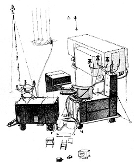
The AN/MPN-14 basically functions as an air-traffic control center for directing
and landing aircraft. The mobile RAPCON trailer, together with the operations trailer
and power trailer, comprise Landing Control Central AN/MPN-14. The mobile RAPCON
trailer provides a centralized operating area from which to control the movement
of aircraft within a 60 mile radius. The equipment contained in the mobile RAPCON
augments the GCA Radar Set to control the movement of air traffic approaching or
departing from an airfield.
Relation to Similar Equipment
The AN/MPN-14 is similar to the AN/MPN-16, difference is in production models.
The AN/MPN-14 and AN/MPN-16 are similar to the AN/MPN-13 and AN/MPN-15, difference
is the mobile RAPCON used with the AN/MPN-14 and AN/MPN-16 but not with the AN/MPN-13
and AN/MPN-15. The AN/MPN-14 is a basic AN/MPN-13 with a mobile RAPCON added. Also,
to adapt it for use with the mobile RAPCON, the radar set has been modified to remote
search and precision indicating functions, performance monitoring signals, and communications
control to the RAPCON van. Additional uhf radio sets have been installed, new telephone
facilities have been provided, and two-way intercom stations have been added to
facilitate maintenance of the equipment. The AN/MPN-13 is a basic AN/CPN-4, AN/MPN-11A,
AN/MPN-11B, or AN/MPN-11C, difference is an improved model incorporating recent
changes such as extended range coverage, additional search cursors, improved receiver
design, and monitoring of the power output, relative tuning, and noise figure characteristics.
Technical Description
Primary AC Power
- Requirement: 120/208v, 4-wire, 3 ph, 60 cps, 30 kw (min) RAPCON trailer only,
66 kw including radar set, regulated to 117 plus or minus 2v for input of 106-132v
- Source: Government furnished diesel engine generator or commercial
DC Power
- Requirement: plus 28v
- Source: plus 28v, 50 amp power supply in RAPCON trailer, or batteries in power
trailer at 10 amp max for emergency conditions.
Communication Frequency
- Transmitting and Receiving: 100 to 156 mc and 225 to 399.9 mc
General Operating Characteristics (Search Radar)
Frequency Range: 2780 to 2820 mc
Power Output: 600 kw (peak)
Range (determined with T-33 type aircraft):
- At 2000 ft, at least 20 naut mi
- At 6000 ft, at least 25 naut mi
- At 10, 000 ft, at least 30 naut mi
- At 25, 000 ft, at least 35 naut mi
Coverage
- Azimuth: 360 deg
- Elevation: Cosecanting to 45 deg
Accuracy
- Azimuth: 1 deg when target range is more than 10 pct of indicator range.
- Range: 4 pct when target range is more than 20 pct of indicator range setting.
Resolution
- Azimuth: 2.3 deg when target range is more than 30 pct of indicator range setting.
- Range: 675 ft target separation or 1 pct of indicator range setting, whichever
is greater.
PRF: 1100 pps plus or minus 2 pct
Amplitude (terminated in 100 ohms): 35v min for at least 0.5 usec at 50 pct of
peak amplitude.
Rise Time: 400v per usec min
Indicator Characteristics (Search Radar)
Display
- Type: 12 in. ppi
- Information: Normal and MTI video, range marks, angle marks, cursors, and IFF/SIF
video.
Sweeps: Rotating linear sweep synchronized with antenna scan
- Ranges
- Range Marks: 5, 10, 20, 40, 60, and 200 naut mi
- Range Mark Calibration:
- 2-mi intervals on 5- and 10-mi ranges
- 5-mi intervals on 20- and 40-mi ranges
- 10-mi intervals on 60-mi range
- 50-mi intervals on 200-mi range
- Off-Centering: Sweep center may be moved to edge of display, approximately doubling
range up to 60 mi max in sector displayed except for 40-, 60-, and 200-mi ranges.
- Angle Marks: At -5 deg, O deg, and plus 15 deg to indicate outline of precision
azimuth coverage with respect to runway parallel.
- Electronic Cursors: Two (or three if 3rd Indicator is used) separate cursors
to indicate desired flight paths.
- Maps: Navigation head and compass rose for mechanical calibration of target
bearing and as provided by video mapper.
General Operating Characteristics (Precision Radar)
Frequency Range: 9000 to 9160 mc
Power Output: 45 kw (peak)
Range (determined with T-33 type aircraft): At least 8 naut mi
Coverage
- Azimuth: 20 deg
- Elevation: 7 deg
Accuracy
- Azimuth: 0.6 pct of target range plus 10 pct of deviation from optimum approach
path.
- Elevation: 0.3 pct of target range plus 10 pct of deviation from glide path.
- Range: 2 pct when target range is more than 5 pct of indicator range setting.
Resolution
- Azimuth: 1.1 deg target separation
- Elevation: 0.6 deg target separation
- Range: 200 ft separation
- Detectable deviation from glide path: 25 ft at one-mi range
PRF: 1833 pps plus or minus 3 pct (precision indicator)
Amplitude (terminated in 100 ohms): 35v min for at least 0.5 usec at 50 pct of
peak amplitude.
Rise Time: 400v per usec min
Indicator Characteristics (Precision Radar):
Display
- Type: Azimuth (lower half) and elevation (upper half) expanded displays combined
on 12 in. CRT with sector limiting to prevent overlap.
- Information: Normal and MTI video, range marks, cursors, and servo data.
Sweeps: Logarithmic timebase sweeps 8-5/16 in. long. At 1 mi, sensitivity is
3 times that of linear sweep at one mile
Range
- Range Marks: Adjustable for any range between 6 and 10 naut mi
- Range Mark Calibration: 1-mi intervals with variable delay between 0 and 55
used (0 to 4.5 mi) with respect to the timebase sweep origin.
Off-Centering: Azimuth scale expanded approx 3 times, with vertex at left and
runway approach course horizontal; elevation up- down scale expanded approx 10 times,
with vertex at left and ground line horizontal. Logarithmic range scales provide
increasing sensitivity with decreasing range.
Electronic Cursors: Separate cursors to indicate azimuth courseline, elevation
glidepath, and glidepath downward deviation limit.
Maps: Separate illuminated maps indicate limits of scan and intervening degree
marks for both azimuth and elevation sectors.
Environmental Conditions
Ambient Temperature
- Operating: Interior, -22 deg to plus 140 deg F (-30 deg to plus 60 deg C)
- Nonoperating: Exterior, -40 deg to plus 140 deg F (-40 deg to plus 60 deg C)
Relative Humidity: 100 pct max under plus 90 deg F (plus 32 deg C)
Barometric Pressure (operating): Sea level to 6000 ft
Salt Atmosphere: As encountered in coastal regions.
Sand and Dust: As encountered in desert regions.
Rain: As encountered in tropical regions.
Installation Considerations
Siting: The mobile RAPCON may be located up to a distance of 500 feet from the
GCA repair set. The mobile RAPCON must never be located within the scan area of
the precision antennas of the radar set. The AN/MPN-14 equipment must
be located a minimum distance of 500 feet from the centerline of any runway,
250 feet from the far edge of any taxiway (350 feet for heavy bomber bases) and
125 feet from the far edge of any apron. These distances are measured to the end
of the AN/IPN-14 equipment nearest the runway, taxiway or apron.
Cabling Requirements: The mobile RAPCON equipment is capable of remote operation
up to a distance of 500 feet, although only 250 feet of cable is supplied.
Principal Components and Physical Data
Communication Control Console AN/MPA-19
Communication Control Console AN/MPA-22
Electrical Equipment Cabinet CY-3365/MPA-17
Antenna Support AB-715/MPN
Power
Supply PP-3016/GPN
Recorder-Reproducer Assembly RO-193/MPN
Amplifier Control
Group AN/MPA-25
Control Indicator Group AN/MPA-9
Electrical Equipment Cabinet
Base MT-2617/MPN
Electrical Equipment Shelf FN-131/MPN
Control-Indicator C-3880/MPN
Power Supply Set AN/MPA-26 1
Control Indicator C-3709/GPN
Controller
Seat Assembly 33443
Radar Set Data Display Board PT-458/MPN
Interconnecting
Cable Set 95113
Intercommunication Station LS-478/MPN
Aircraft Obstruction
Marker Light MX-3652/MPN
Communications Control Console AN/MPA-20
Communications
Control Console AN/MPA-21
The remaining Principal Components consist of the Search
Radar, Precision Radar, Antennas, and Communication
Equipment of either one of
the following sets which have been completely modified into the AN/MPN-13. They
are
the AN/CPN-4 models, AN/MPN-11A, AN/MPN-11B, and some models of the AN/MPN-11C.
Antenna Support (vhf) AB-194/GPN
Antenna Base AB-195/GPN
Antenna Support (uhf)
AB-333/GPN
Radar Test Set AN/GPN-16
Antenna Horn AS-513/GPN
Antenna (Azimuth)
AS-519/GPN
Antenna (Elevation) AS-520/GPN
Antenna (uhf) AT-197/GR
Antenna
AT-282/GPN
Antenna AT-283/GPN
Antenna Reflector (Search) AT-284/GPN
Antenna
AT-285/GPN
Antenna Reflector (Azimuth) AT-290/GPN
Antenna Reflector (Elevation)
AT-291/GPN
Radio Set Control C-872/GPN
Signal Comparator CM-35/GPN
Directional
Coupler CU-266/GPN
Signal Data Converter CV-142/GPN
Air Conditioner HD-78/G
Electric Exhaust Fan HD-98/GPN
Electric Exhaust Fan HD-222/GPN
Air Conditioner
HD-237/MPN-11C
Azimuth Elevation-Range
Indicator IP-127/GPN
Azimuth Elevation-Range
Indicator IP-128/GPN
Indicator Group OA-230/GPN
Indicator Group (Search) OA-231/GPN
Synchroscope Set OA-233/GPN
Antenna Group OA-235/GPN
Transmitter Group OA-243/GPN
Comparator-Power Supply Group OA-244/GPN
Comparator-Power Supply Group OA-245/GPN
Dynamotor Power Distribution
Group OA-251/GPN
Radar Set Group OA-257/GPN
Radar Set Group OA-258/GPN
Radar Set Group OA-259/GPN
Radar Set Group OA-262/GPN
Indicator Control Group OA-271/GPN
Radar Set Group OA-276/GPN
Direction Finder
Group OA-277/GPN
Radar Set Group OA-279/GPN
Antenna Group OA-634/MPN-11
Antenna Group (Elevation) OA-6-142/MPN-11
Antenna Group (Azimuth) OA-6, 13/MPN-11
Radar Set Control Group OA-6441/MPN-11
Power Supply (10 kw) PP-607/GPN
Power
Supply (28v, dc) PP-1383/MPN- 11C
Engine Generator PU-211/G
Radio Receiver-Transmitter
RT-178/ARC-27
Power Distribution Panel SB-50ot/MPN-11C
Electrical Synchronizer
SN-87/GPN
Electrical Synchronizer SN-88/GPN
Radar Transmitter T-289/GPN
Sweep Generator TD-50/GPN
Sweep Generator TD-51/GPN
Pulse Generator TD-57/GPN
Map Generator TD-5cl/GPN
Map Generator TD-58A/GPN
Antenna Drive (Search) TG-11/GPN
Antenna Drive (Precision) TG-12/GPN
Cargo Trailer (Operations) V-96/MPN-11
Cargo Trailer (Power) V-97/MPN-11
Cargo Trailer (Power) V-121/MPN-11C
Reference Data and Literature
Technical Orders: 31P5-2MPN14- Series
Posted February 20, 2022
|


