|
Electricity - Basic Navy Training Courses NAVPERS 10622 |
||||||||||||||||||||||||||||
|
Here is the "Electricity - Basic Navy Training Courses" (NAVPERS 10622) in its entirety. It should provide one of the Internet's best resources for people seeking a basic electricity course - complete with examples worked out. See copyright. See Table of Contents.
¶ U.S. GOVERNMENT PRINTING OFFICE; 1945 - 618779
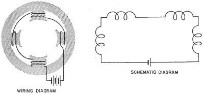
CHAPTER 4 (* VERY IMPORTANT NOTE: Current flow here is defined as from negative to positive, which is opposite of today's convention. Modern convention of positive-to-negative current flow, with negative-to-positive electron flow requires a "right-hand rule." See Right-Hand Rule page on RF Cafe). THE ELECTRICAL CIRCUIT DIAGRAMS Men who know electricity best, "talk with diagrams." Ask them a question and they whip out a pencil and make a quick sketch to show you what's what. In telling a technical story, a single diagram is often worth more than a thousand words in putting over the POINT of the story. Electricians may use either one of two types of diagrams to explain electrical installations. When you are installing or repairing equipment you will use one or the other of these electrical "blueprints." The two types are WIRING DIAGRAMS and SCHEMATIC DIAGRAMS. You MUST understand both types of diagrams before you go any further with your study of electricity. Certain STRUCTURAL PARTS of a circuit, as well as the ELECTRICAL CONNECTIONS are shown in a WIRING DIAGRAM. In a SCHEMATIC DIAGRAM, however, ELECTRICAL CONNECTIONS and ELECTRICAL APPARATUS are shown by symbols and all structural parts are eliminated The two diagrams in figure 14 show exactly the same thing. Both the wiring diagram and the schematic diagram illustrate the connection pattern of the coils in an electric motor. Notice how the schematic diagram uses a form of shorthand.
Figure 14. - Two types of diagrams.
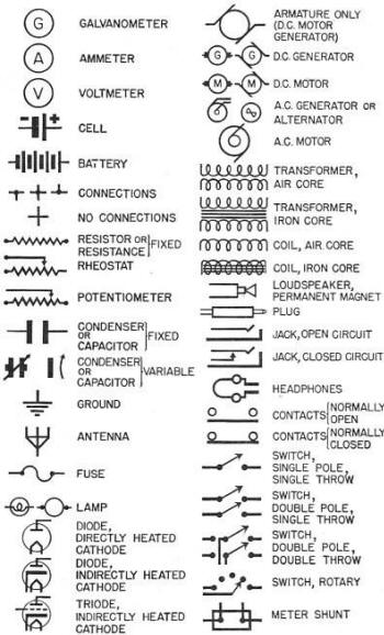
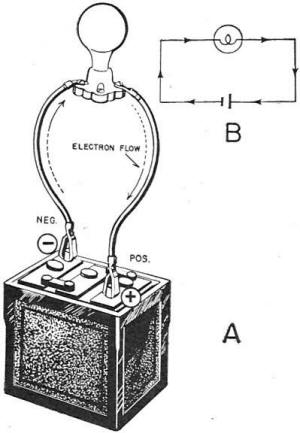
Figure 15. - Electrical and radio symbols. Figure 15 is a table of electrical and radio symbols. When you study schematic diagrams in this book, you will find it profitable to look up any symbols you don't recognize. THE COMPLETE CIRCUIT All normal electrical circuits are COMPLETE circuits. They have one path from the source of power to the load and another path from the load to the source of power. Examine A and B of figure 16. Note that "the battery is the source of power. Following the arrows through the circuit, you find that the current leaves the negative terminal flows through a wire to the lamp, through the lamp to a second wire and back through this wire to the positive terminal of the battery. This path of current is a COMPLETE CIRCUIT. You may ask, "Why is it necessary to provide a return path for the current to get back to the battery?" Consider what would happen if there were no return path. The current would pile up at the lamp until the potential of the lamp would, equal the potential of the battery. This would take only a split second. With equal potentials on lamp and battery, NO current would flow-and the lamp would not light. It is evident that all circuits which carry current must be COMPLETE paths from SOURCE TO LOAD AND BACK TO SOURCE.
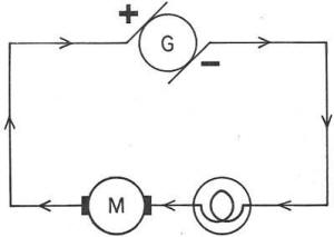
Figure 16. - Direction of current flow*. Figure 17 shows a circuit in which a lamp and a motor are supplied with power from a generator. Note that the current flows from the negative side of the generator, first through the lamp and then through the motor, and completes the circuit by returning to the positive side of the generator. In the circuits just described, two different sources of potential difference were used-the generator and the battery. Almost every circuit uses either a generator or a battery as its source of potential. Either one furnishes the force which drives current through the circuit. Generators and batteries correspond to the pumps in a water system.
Figure 17. - Current direction with two loads*. A generator or a battery builds up a CONTINUOUS high negative potential at its negative terminal. At the same time, a CONTINUOUS high positive potential is built up at the positive terminal. These two potentials are brought about by an electron transfer WITHIN the battery or generator. With these high potentials at either end, the circuit is in a strained condition-too many electrons at the negative terminal and too few electrons at the positive terminal. This strain can be relieved only by a return to a neutral (normal) condition-equal numbers of electrons and equal numbers of protons at both terminals. Since only electrons move in an electrical circuit-there is a CONTINUOUS flow of ELECTRONS THROUGH THE CIRCUIT FROM THE NEGATIVE TERMINAL TO THE POSITIVE TERMINAL. This is the rule you will use in tracing the current flow in all electrical circuits in this book.
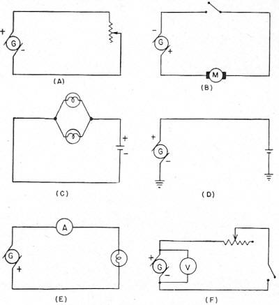
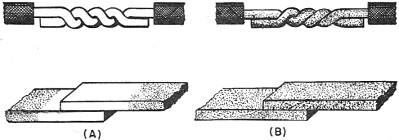
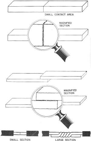
Figure 18. - Practice circuits. Circuit diagrams are the "blueprints" of the electrician and radio technician. They guide him in all installations, operations, and repairs of electrical equipment. Figure 18 shows six different circuits. Practice on them. By referring to the table in figure 15, you should be able to understand the following facts about each circuit - 1. Direction of current flow. 2. Type of potential source. 3. Kinds of loads on. the circuits. 4. Connection patterns. 5. Circuit controls (switches, fuses, etc.). 6. Cable specifications- (you will learn later). 7. Special devices (especially in radio circuits). CIRCUIT FAULTS Electrical circuits, in good working order, are known as CLOSED or COMPLETE circuits. Your circuits should always be in good working order. You can install and maintain your circuits properly by paying intelligent attention to your work. Don't let a circuit fault be YOUR fault! Circuit faults are anything that causes the circuit to OPEN, GROUND, or SHORT. The effect of these faults is to decrease or cut off the current, or to increase it beyond a safe value. Sometimes-not often-faults are unavoidable. In your circuits, make sure that ALL the faults are UNAVOIDABLE. OPEN CIRCUITS Open circuits may result from dirty or loose connections and from sloppy or careless runs of cable. Proper connections are made through binding posts, plugs, switches, receptacles, and soldered or friction lugs. Splicing is NOT permitted aboard Naval vessels except in a real emergency (damage control). Good connections are CLEAN and TIGHT. If a connection is perfectly clean, contacts over a large area, and is tight, NO RESISTANCE IS ADDED to the circuit. But if the connection is dirty, of small contact area, or is loose, a considerable amount of resistance is introduced in the circuit. Usually dirt -oil, corrosion, or dust-is a good insulator. If such insulation remains between two connected parts of a circuit, as in B of figure 19, only a small amount of current may pass. Dirty connections can be avoided by rubbing the connecting parts with a piece of sandpaper or by scraping them with the back of a knife blade until they are bright. Dirty connections are not true opens, but they are classified as opens because they reduce current. Loose connections may occur at the knives of switches, spring clips, and bolt terminals; and also at emergency splices. Loose connections can be avoided if you use good common sense. Check your connections at all points before energizing the circuit.
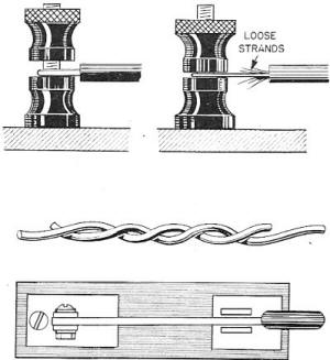
Figure 19. - Clean and dirty contacts. After electrical apparatus has been in operation for some time, vibrations may have produced loose connections. It is easy to spot a loose connection. It sparks, gets hot, and the current strength drops below its rated value. Loose connections, because of their arcing, are fire hazards and may burn insulation. Figure 20 shows a few kinds of loose connection.
Figure 20. - Loose connections. If greatly magnified, as in figure 21, the surface of a conductor looks rough and ragged. When two parts of a circuit are joined together, as in figure 21, the area of the contact surfaces at the joint, must be large-remember, only the HIGH SPOTS of each surface touch. By increasing the surface in contact, more high spots touch and the resistance of the connection is reduced. Solder, flowed into a connection, brings all surfaces - high or low - into contact. Soldered connections are the tightest connections.
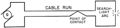
Figure 21. - Contact resistance. The true open circuit occurs when a wire breaks or when a connection comes completely apart. The circuit is broken and no current flows. Opens may also result from poor running of cable. Cable should have no kinks or sharp bends, which 'might weaken and break. SHORT CIRCUITS SHORT CIRCUITS are "short-cuts" between the two terminals of a generator or a battery. Imagine that the insulation is destroyed within the search light cable run. The two conductors within this cable contact each other. Figure 22 shows this schematically. The current in this circuit. now travels from the source to the SHORT (point of contact) and back to the source. The short has provided an easier path of low resistance.
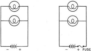
Figure 22. - Short circuit. The current is extremely high because the short offers practically no resistance to the current. This current may be high enough to heat the wires to a red-heat, melt the insulation, burn out the generators, and sometimes cause a fire. To prevent damage from shorts, a FUSE is inserted in the line usually close to the generator or battery. A fuse is simply a piece of metal which melts at a fairly- low temperature. Fuses are designed to carry specified amounts of current. Standard current ratings for fuses usually are multiples of five - 5, 10, 15, 20, etc. amperes. A 10 ampere fuse will carry any current up to 10 amperes; but any current over 10 amperes will melt the fuse metal and open the circuit. Thus, the fuse, by melting first, prevents the other parts of the circuit from over-heating. Overloads on a circuit-too many electrical devices connected in the same circuit will also "blow" fuses. Figure 23 shows a fuse protected circuit and a non-protected circuit. All Navy lighting circuits are protected by fuses. Most shorts are accidental. They occur when vibration wears away insulation, when salt water gets into a connection of cable, when heat melts away insulation, and when carelessness brings two conductors together. Common sense and reasonable care will reduce shorts to a minimum.
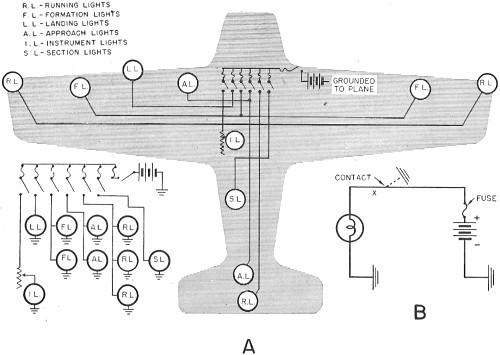
Figure 23. - Unprotected and protected circuits GROUNDED CIRCUITS Grounded circuits are both intentional and accidental. Intentional grounds are used on airplanes and small motor launches. One terminal of the battery or generator is connected to the fuselage of the airplane or to the motor or hull of the launch. The fuselage, motor, or hull constitutes a GROUND connection. The other terminal of the source is connected to the loads which are also grounded. The current path is from source to load via a wire and return to source via the metal framework (ground). Actually the metal framework is being used as one of the two conductors. An accidental ground from the "hot" side (ungrounded terminal) to the framework would be a short circuit through the plane or launch. Of course, the fuses would blow.
On regular ships of the Navy, no power circuits are grounded. In fact, all Circuits are periodically tested to locate and correct accidental grounds. The danger lies in the possibility of the hot side of circuits being grounded. Result - a short circuit. Note the difference between intentional grounds and accidental grounds in figure 24.
Figure 24 – Intentional and accidental grounds SUMMARY OF CIRCUIT FAULTS Opens, shorts, and accidental grounds either interrupt a circuit 'completely or, at least, impair its efficiency. In addition, circuit faults are fire hazards-not to be tolerated aboard ship. In general, there are only a few causes of circuit faults. Review the table below and be able to prevent circuit faults on your job.
CIRCUIT FAULTS AND CAUSES
CABLE DESIGNATIONS Blueprints of wiring diagrams always carry a group of letters and numbers alongside each conductor. These letters and numbers tell you exactly the kind of cable used on the run. The cables them-selves bear a metal or fiber tag stamped with the same letters and numbers. The first letter tells how many conductors are in the cable. "S" stands for single conductor, "D" stands for double conductor, "T" stands for triple conductor, "F" stands for four conductors, and "M" stands for multiple (more than four) conductors .to the cable. Two "T" 's together at the beginning stand for twisted pair, telephone. The middle letters indicate the use of the cable. Examples are, "LP" for lighting and power, "RH" for radio-high tension, and "HF" for heat and flame resistant. The last letters indicate the outside covering. "A" means armored, "L" means leaded, "F" means flexible. The numbers following the letters tell you two things-the number of conductors ( used ONLY if more -than four) and the cross section area of each conductor in thousands of CIRCULAR MILS. The following table gives you a number of examples of Navy cables. If you keep the marking system in mind, you will be able to reason out ANY cable markings. NAVY CABLE MARKINGS
Chapter 4 Quiz
|
||||||||||||||||||||||||||||