Ponderings on Power Measurements |
|
Sunshine Design Engineering Services
Joe Cahak, owner of Sunshine Design Engineering Services, has submitted another fine article for posting here. Joe has many years of automated RF testing experience to leverage when writing this paper on the basics of power measurement. See list of all of Joe's articles at bottom of page. Ponderings on Power Measurements By Joseph L. Cahak Copyright 2013 Sunshine Design Engineering Services Pondering on Power Measurements
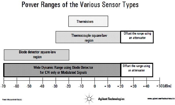
Figure 1 - Power Sensor type and Range courtesy Agilent Technologies
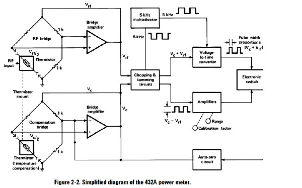
Figure 2 - Thermistor Power Meter Schematic courtesy Agilent Technologies
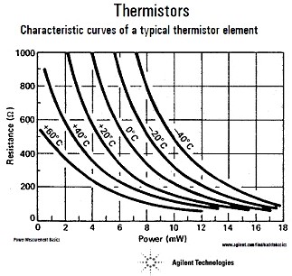
Figure 3 - Thermistor temperature response courtesy Agilent Technologies
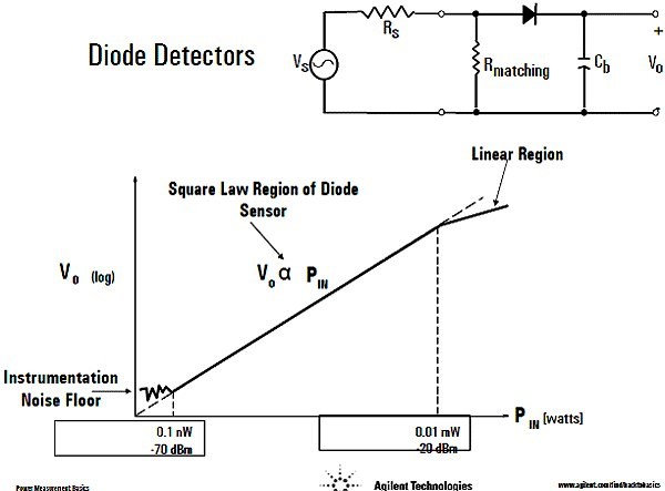
Figure 4 - Diode Power Sensor courtesy Agilent Technologies
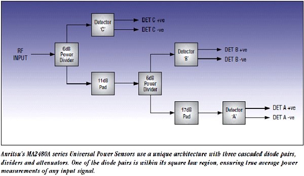
Figure 5 - Universal Power Sensor Range courtesy Anritsu
Figure 6 - Universal Wide Power Range Sensor courtesy Anritsu
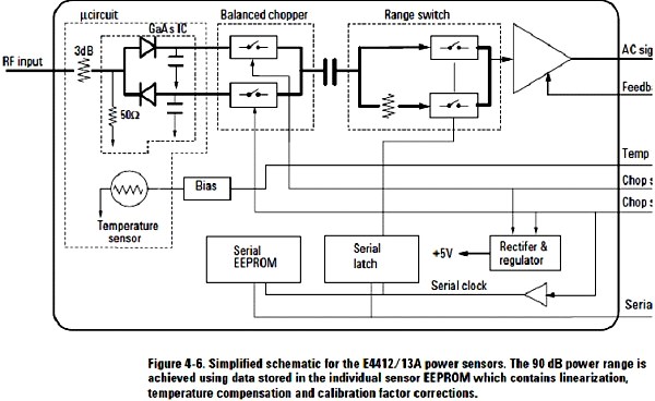
Figure 7 - E4412/13 Sensor Architecture courtesy Agilent Technologies
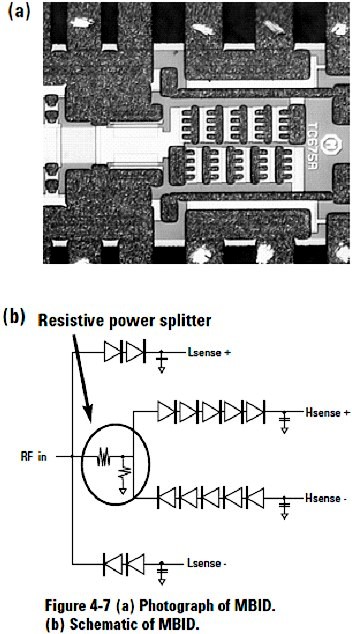
Figure 8 - Sensor for E4412/13 Power Sensor courtesy Agilent Technologies
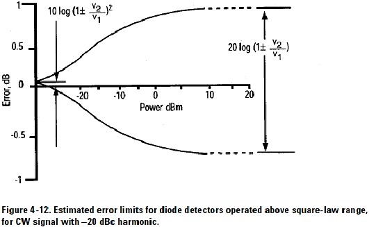
Figure 9 - Diode Sensor Error with harmonic signal present courtesy Agilent Technologies
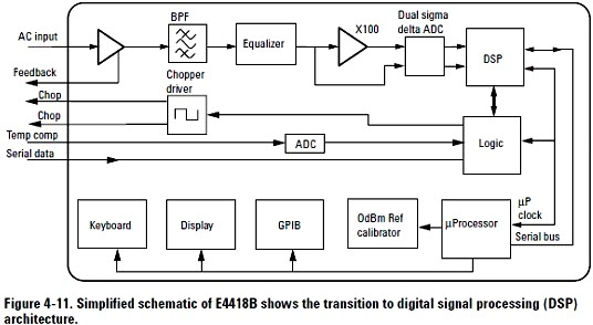
Figure 10 - DSP Power Measurement courtesy Agilent Technologies
Figure 11 - Power Mismatch Curves for Anritsu Detector courtesy Anritsu A power measurement is a scalar quantity and is a measure of power detected. These measurements can be made a variety of ways. Most of us are familiar with the notion that voltage (volts) multiplied by current (amps) is power (watts) and power multiplied by time is energy. At DC or low frequencies these power measurements from the current or voltage is relatively easy and not very complicated. As we get to higher frequencies the typical means of measuring voltage or current breakdown and are not accurate. The power measurement inaccuracies are due to frequency response of the detectors at high frequency and also the impedance match of the detectors as well as the instantaneous frequency response of the detector network. All power sensors are broadband sensors. They cannot discriminate between individual signals in a multiple signal environment. These signals can add or subtract from the total power as a combination of the power depending if the signals are in or out of phase. Power measurement in the RF and Microwave frequency range are typically made with thermistor, thermocouple or diode based instruments. The thermistor or thermocouple based power sensors are most accurate for “true” or RMS power. True power is properly integrated (modulation envelope) over time to give the' true' power no matter the waveform shape. If the signal is a CW (continuous wave) signal that does not vary in signal strength or frequency, the measurement is relatively easy and the RMS value is easy to compute. In the case of more complicated modulated signals or complex waveforms, computing or measuring True RMS power gets more difficult and complicated. To better understand this we will review the methods of measuring RF Power. Thermistor and Thermocouple Devices The most accurate methods of measuring True RF power is with devices called a thermistor or a thermocouple. These devices converts RF power to thermal power (heat) and the thermal power is converted to a resistance or a voltage difference measurement that can be measured and converted to the power measured. There are issues associated with this method of measuring RF power. The first issue with this method is a limited dynamic range that it will accurately measure over. Most of the sensors in the market today that use thermistor based sensors have a measurement range of -30 to +20 dBm. Some measure higher power levels with an attached calibrated attenuator. Microprocessors and EEPROM calibration tables are used to perform power correction for temperature and frequency response. With RF power to thermal conversion, there is a small time lag for the thermal response from the RF power. While this is a small sensor with a small thermal mass in the sensor, nonetheless this equates to a small lag in the power response. This property will affect accuracy of rapidly varying signals, and signals with complex modulation. Finally, there is a frequency response associated with the sensor and also the impedance match of the interface to the sensor. These responses can be calibrated and removed using a cal factor for the sensor. Diode Devices Another method of measuring power is with a diode sensor. These diode sensors have a faster response time than thermistor based sensors, but due to the diode characteristics, they have more impedance match issues than the thermistor. The diode has low impedance compared to the 50 ohm characteristic Impedance of most RF instruments and RF networks in use today. This means that some form of matching network must be used to improve the match into the sensor and DC isolation (blocking). These components have frequency sensitivity. The diode is sensitive to VSWR and is more prone to measurement error due to these issues. Another issue is the non-linearity of the diodes. What that means is at higher power levels the diodes conduct and the current is no longer square law proportional to the voltage of the detected signal. This has ramification with measuring complex signal environments. Recall the power equation from voltage: Power = V2/R = I2*R This implies that while the diode is in the square law region the voltage output from the rectification is directly proportional to the power in that region only. Outside that region, the power is not directly linear to Voltage. Making power measurements in the quasi and linear regions of the diode response is less accurate when the signal input is modulated with wide bandwidth signals or multiple tone signals. To make these measurements, the instrument must have the dynamic measurement power range and the frequency response to be quantifiable, repeatable and correctable. For the diode sensors, extensive EEPROM correction tables are used for the frequency, signal levels and temperatures at which the power measurements will be made. In many cases these corrections are not adequate for very wideband devices such as Ultra Wideband USB or some of the other digital modulation formats. Most sensors have an instantaneous bandwidth that they can respond to which typically range from 10 MHz to 30 MHz for most power sensors available on the market. This is not important for most measurement markets. With modulation formats wider than this and higher in power than the square law region, pulsed power or sensor instantaneous bandwidth can have varying amounts of error. Recall the comment above regarding operation above the square law region. The trick that can be used to gain some level of better power accuracy for modulated signals with diode sensors is to keep the power within the square law region (-70 to -20 dBm). Analog Devices has recently come out with a replacement for the Schottky diodes to measure power. The ADL6010 is a coplanar input for measuring power from 500MHz to 50GHz. It features built-in linearization for added accuracy. DSP Devices One trend is communication power measurements is to use DSP (digital signal processing) architecture to process the signals and get a better measure of power with complex formats and frequency components. These can also provide the ability to measure the peak or envelope power and crest power on multiple tones or modulated signal measurements. They can also offer wider bandwidths than traditional sensors. Capability is only limited by the sampling rate, bit depth and accuracy of the ADC's or Sigma-D samplers. Peak Envelope Power and Peak or Crest Power Other RF Power measurements are peak envelope power (PEP) and peak or crest power. These are used to measure the power of multi tone and digitally modulated waveforms to get the instantaneous power maximum of the system. There are many instances where a power measurement that takes the peak power value of the envelope is needed. All digitally modulated waveforms, AM and single sideband (SSB) use this measurement. The peak measurement is also the crest power, which would be compared to the average power to calculate the crest factor of the RF device, which is the ratio of the peak power level above average power. These peaks can damage power amplifiers if not contained in amplitude. Instantaneous or Video Bandwidth Instantaneous or video bandwidth (VBW) is the response after rectification of the signal and the detection circuitry response and ability to integrate the RMS power. This video modulated rectification result is used to calculate the power. If the detection circuitry downstream of the rectification has poor frequency response, the accuracy of the power measurement will degrade. Typical video bandwidth range is 10 MHz up to 100 MHz video or instantaneous bandwidth. The user must be aware of the signal measurement equipment requirements to account for this signal bandwidth and to thereby ensure accurate power measurements of modulated signals. If measuring pulsed power the Video or instantaneous bandwidth should be at least 5x the pulse repetition rate. Measurement Accuracy The quality or accuracy of the power measurement depends not only on the power sensor calibration factors previously mentioned. Another significant source of measurement error is the sensor impedance match and the match of the device port under test. This mismatch error is computed with the formula Mismatch Error= 10log(1±ρgρl)2 . The + and – represent the max and minimum mismatch for the measurement mismatch loss of power measured. ρg and ρl are the generator and load reflection coefficient. Agilent Application Notes:
Sunshine Design Engineering Services is located in the sunny San Vicente Valley near San Diego, CA, gateway to the mountains and skies. Are you looking for new things to design, program or create and need assistance? I offer design services with specialties in electronic hardware, CAD and software engineering, and 25 years of experience with Test Engineering services in RF/microwave, transceiver and semiconductor parametric test, test application program development, automation programs, database programming, graphics and analysis, and mathematical algorithms. See also: - Noise and Noise Measurements - Measuring Semiconductor Device Input Parameters with Vector Analysis - Computing with Scattering Parameters - Measurements with Scattering Parameters - Ponderings on Power Measurements - Scattered Thoughts on Scattering Parameters Sunshine Design Engineering Services 23517 Carmena Rd Ramona, CA 92065 760-685-1126 Featuring: Test Automation Services, RF Calculator and S-Parameter Library (DLL & LLB)
Posted June 9, 2020 |