Module 16 - Introduction to Test Equipment
|
||||||||||||||||||||||||||||||||||||||||||||||||||
|
Module 16 − Introduction to Test Equipment Pages i, 1−1, 1−11, 1−21, 2−1, 2−11, 2−21, 3−1, 3−11, 3−21, 3−31, 4−1, 4−11, 4−21, 5−1, 5−11, 5−21, 5−31, 6−1, 6−11, 6−21, 6−31, 6−41, Index
Chapter 1
Test Equipment Administration and use
Learning Objectives
Learning objectives are stated at the beginning of each chapter. These learning objectives serve as a preview of the information you are expected to learn in the chapter. The comprehensive check questions included are based on the objectives. By successfully completing the NRTC, you indicate that you have met the objectives and have learned the information.
Upon completing this chapter, you should be able to:
1. Describe the Ship Configuration and Logistic Support Information System (SCLSIs).
2. State the differences between calibration and repair.
3. Explain the various calibration status labels used by the Navy.
4. List the procedures for obtaining repairs to test equipment.
5. Describe the Metrology Automated System for Uniform Recall and Reporting (MEASURE) System and the purpose of the Metrology Equipment Recall and Reporting (METER) card and recall schedule.
6. Describe major test equipment references available to you.
7. Explain the purposes and benefits of testing.
8. State the safety precautions involved in working with test equipment.
9. List three precautions you should observe to avoid damaging electric measuring instruments.
10. State the correct procedures for using a safety shorting probe.
11. Describe resistance, voltage, and current measurements in terms of purposes, methods, and instruments used.
12. Describe how capacitance and inductance are measured.
13. Explain the operation of bridges in the measurement of unknown resistances, capacitances, and inductances.
Introduction
One purpose of this chapter is to acquaint you with the practical use of test equipment. The presence of adequate test equipment in your shop is not in itself a "cure-all" for making repairs to complex electronic equipment. You must know how to best use the equipment available. First, however, you must understand the basis of electronic theory and be able to apply it to the system under repair.
Another purpose of this chapter is to introduce you to calibration and repair procedures, and basic voltage and current measurements. You will also learn how ac bridges are used for precise measurements of resistance, capacitance, and inductance.
Much of the theory of operation and practical applications of the basic types of test instruments used in electrical and electronic circuits are found in the instruction books and technical manuals that accompany various equipment. You should read and understand these books before you attempt to use any test instrument. You should also know the established safety precautions to ensure your safety and safe equipment operating procedures to protect equipment from damage.
Test Equipment IDENTIFICATION
One of the first things you must learn as a maintenance technician is how to identify the various electronic equipment and components by their appropriate nomenclatures. You will find that several methods are used to identify test equipment used; this may be somewhat confusing to you at first. For example, a Tektronix Model 541A oscilloscope can also be identified as a CBTV-541A. The Joint Electronics Type Designation System (JETDS) is used by all branches of the military to identify equipment by a system of standardized nomenclatures.
Q-1. What system is currently used by all branches of the military to identify test equipment?
ELECTRONIC Test Equipment Classification
The Electronic Test Equipment Classification Board was established in 1973 to control the increased use of undesirable electronic test equipment (ETE) in fleet and shore activities. The board classifies electronic test equipments as GENERAL PURPOSE (GPETE) or Special PURPOSE (SPETE) and assigns responsibility for their management. Items classified as general purpose are managed by the Space and Warfare Systems Command (SPAWARSYSCOM). Items classified as special purpose are managed by the individual systems command that generates the requirement.
GPETE is test equipment that has the capability, without modification, to generate, modify, or measure a range of parameters of electronic functions required to test two or more equipments or systems of basically different design.
Special-purpose electronic test equipment (SPETE) is specifically designed to generate, modify, or measure a range of parameters of electronic functions of a specific or peculiar nature required to test a single system or equipment. These special test equipments are procured by the systems command that has the responsibility for the system/equipment requiring the SPETE for maintenance.
Q-2. Name the two classes of test equipment.
Q-3. What test equipment is designed to generate, modify, or measure a range of parameters of electronic functions of a specific nature required to test a single system or equipment?
Until the ETE classification board was established, the uncontrolled increase in use of nonstandard GPETE had resulted in loss of inventory control and increased support costs. NESEA has the responsibility for evaluating requests to purchase nonstandard GPETE and for recommending its approval or disapproval to NAVSEA. NAVSEA will then forward its final decision to the originating command for such requests.
SHIP Configuration and LOGIsTIC INforMATION System (SCLSIs) PROGRAM
The Navy must maintain, update, and calibrate thousands of pieces of equipment. To do this, the SHIP Configuration and LOGIsTIC SUPPORT INforMATION System (SCLSIs) program was designed to keep track of all installed and portable equipment in the fleet. SCLSIs is used to keep up with the existence, location, and changes made to equipment. The SCLSIs program seeks to improve the quality of equipment reporting, provide information needed by other Navy management systems, and reduce record keeping. It is also designed to assist Navy supply systems that furnish spares, documentation, and training necessary to support installed and portable equipment.
Therefore, the inventory of assigned test equipment on board ship is directly related to SCLSIs records. Properly maintained SCLSIs records also show the complete inventory of test equipment on board by quantity, serial number, and location. The SCLSIs program has two basic elements: (1) VALIDATION, to establish a baseline data inventory, and (2) INVENTORY UPDATING, to correct errors or omissions and to document configuration changes.
Q-4. Name the two basic elements of the SCLSIs program.
CALIBRATION and REPAIR PROCEDURES
The difference between the terms calibration and repair needs to be addressed before we proceed further. Calibration is little more than checking, adjusting, or systematically aligning a test instrument to a known standard. To do this, you must ensure that the equipment you send to the calibration lab is in working order.
The calibration lab is where actual repair work becomes important. Obvious problems, such as open power cords, burned components, broken meters, and missing hardware, should be repaired or replaced before sending equipment to the calibration lab. Most calibration labs with which you will deal will be part of an intermediate maintenance activity (IMA) on board a tender.
CALIBRATION STATUS
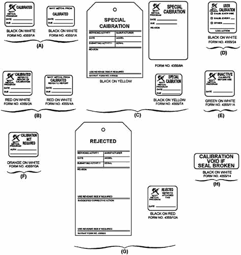
You can determine the calibration status of any test equipment by checking the calibration label or tag located on the equipment. These calibration labels or tags advise you as to whether the item is usable and within its calibration interval. Tags and labels to be used in the METROLOGY CALIBRATION (METCAL) coordination program are listed in the following paragraphs. No other calibration labels or tags are authorized to be placed on test equipment.
Calibrated Label
The CALIBRATED label, shown in view a of figure 1-1, has black lettering and a white background and comes in two sizes. It is the most commonly used label in the METCAL program. This label indicates that the instrument to which it is attached is within its applicable tolerance on all parameters. If there are any qualifying conditions for use of the instrument, one of the other labels described in the next paragraphs should be used.
1-3
Figure 1-1. - Calibration labels and tags.
Calibrated - Refer to Report Label
The CALIBRATED - REFER to REPORT label, shown in view B of figure 1-1, has red lettering and a white back ground. It comes in two sizes and is used when you must know the actual measurement values to use the instrument.
Q-5. What calibration label is used when actual measurement values must be known to use the test equipment?
Special Calibration Labels
Two Special CALIBRATION labels are shown in view C of figure 1-1 that have black lettering and a yellow background; the size and content of the labels are different. a Special CALIBRATION tag (figure 1-1, view C) is used with the smaller of the two labels. These labels or tag are used when some unusual or special condition in the calibration should be drawn to your attention.
Such special conditions may be deviations from usual calibration tolerances, multiple calibration intervals, or a requirement for in-place calibration. The special condition that resulted in the Special CALIBRATION label should be described on the large label when sufficient space is available on the instrument or on the tag when the small label is used. Brief descriptions of special conditions are provided in the following paragraphs.
Q-6. An instrument that must be calibrated in place requires what type of calibration label?
In cases where you do not require full instrument capability, the calibration can be performed with reduced tolerances or cover less than all ranges and parameters. This approach is often used when the instrument does not meet full calibration tolerances on certain ranges or parameters, but can still meet user requirements. On the other hand, the special calibration may be for higher accuracy than usual on a short-term basis upon your specific request.
MULTIPLE CALIBRATION INTERVALS. - Some instruments have components that require calibration less frequently than the rest of the instrument. For example, the attenuator in a signal generator may require calibration every 12 months, whereas the rest of the instrument parameters should be calibrated every 4 months. Since the attenuator calibration is time consuming and may require unavailable standards, use of the multiple-interval approach can save considerable time (man-hours) as well as permit the more frequent calibration to be performed at a lower level laboratory.
When a specific instrument has been designed for multiple calibration intervals, such information is provided in the applicable calibration procedure. The Special CALIBRATION label or tag is annotated with the words MULTIPLE INTERVAL, and the type of calibration performed is indicated; for example, partial 1 of 2, 2 of 2, complete calibration, and so forth. The calibration due date reflects the due date of the next partial or complete calibration.
CALIBRATION IN-PLACE. - Some instruments should be calibrated in-place. Annotation on the Special CALIBRATION label or tag will alert both you and the calibrator that the instrument should not be removed, but should be calibrated in-place.
User Calibration Label
Some test and measuring equipment (T&ME) should be calibrated by you instead of your referring the instrument to a calibration facility. For example, some instruments, such as hardness testers and densitometers, are provided with their own standards and should be calibrated each time used, or at least very frequently. Some instruments, such as oscillographic recorders, may require calibration before, during, and after each use.
Other automatic test equipment (ATE) have self-calibration tests that should be performed each time used or each day of use. Still other instruments are calibrated as part of checkout procedures performed daily or weekly and recorded in maintenance logs. Whenever recognized, the requirement for calibration
by the user and the calibration interval (each use - daily, weekly, every 100 hours - each overhaul, and so forth) is indicated in the Metrology Requirements List (METRL).
The useR CALIBRATION label, shown in view D of figure 1-1, has black lettering and a white background and is affixed when the calibration is performed by the user; however, this label is not replaced at each calibration. When the label is first attached to the instrument, it is annotated as to the appropriate calibration interval. Records of calibrations performed, when other than each time used, should be by normal maintenance practices; that is, in the maintenance log, on maintenance action forms, and so forth.
Inactive - Calibrate Before use Label
In the event that an individual instrument due for recalibration will not be used for some time in the future, you may indefinitely postpone the recalibration by affixing an inactive label to the instrument. As shown in view E of figure 1-1, the INACTIVE - CALIBRATE BEforE use label has green lettering and a white background. The INACTIVE label remains on the instrument until it is recalibrated. The instrument is not to be used while bearing this label.
Calibration Not Required Label
Test equipment standards and T&ME not requiring calibration are shown as CALIBRATION NOT REQUIRED. This label, shown in view F of figure 1-1, has orange letters and a white background. It is attached to and should remain on the instrument indefinitely unless its calibration requirements change. If the instrument is not listed in METRL, you should use the following criteria when placing instruments in the CALIBRATION NOT REQUIRED category:
· The device is "fail-safe"; that is, operation beyond specified tolerances will be apparent to the user.
· All measurement/stimulus circuits are monitored during use by calibrated instruments or are dependent on external known or calibrated sources for performance within required limits. (When determining that an instrument falls into the CALIBRATION NOT REQUIRED category, you should annotate the label as to the authority for the decision, such as METRL, technical manual, letter or message from higher authority.)
Rejected - refer To Attached Tag Label
In the event that an instrument fails to meet the acceptance criteria during calibration and cannot be adequately repaired, a REJECTED - REFER to ATTACHED TAG label is placed on the instrument and all other servicing labels removed. This label, as shown in view G of figure 1-1, has black letters and a red background. In addition to the REJECTED label, a REJECTED tag, giving the reason for rejection and other information as required, is attached to the instrument. Both the label and tag remain on the instrument until it is repaired and recalibrated. The instrument is not to be used while bearing a REJECTED label.
Calibration Void If Seal Broken Label
The CALIBRATION VOID IF SEAL BROKEN label, shown in view H of figure 1-1, has black letters and a white background. It is placed over readily accessible (usually exterior) adjustments to prevent tampering by the user when such tampering could affect the calibration. The label should not be
1-6 used to cover adjustments or controls that are part of the normal use and operation of the instrument. This label may also be used to prevent removal and/or interchange of plug-ins, modules, subassemblies, and so forth, when such removal or interchange would affect the calibration.
REPAIR PROCEDURES
If you are unable to replace a known failed component with onboard spares, you can often locate the replacement component from other supply sources. The replacement component can then be delivered, along with the inoperative equipment, to the IMA. So by sending the repair part along with the equipment, you can reduce repair time considerably. This is particularly true when your unit is getting under way and no time is available for you to complete the repair before calibration. Most operational commands have a higher supply priority for purchase of repair parts than the IMA can use.
"No Reject" Policy
IMAs have a "no reject" policy on test equipment to provide operational test equipment in a more timely manner. The "no reject" policy says, in effect, that test equipment submitted to the IMA for calibration, which is later found to require repair, will be repaired by the repair department of the IMA. Before this policy, any equipment found inoperative by the calibration lab was marked REJECTED, the reasons stated, and the equipment returned uncalibrated to the ship for repairs. The "no reject" policy does not relieve you of your responsibility to ensure your equipment is in working order prior to submitting it for calibration. Its purpose is to streamline the procedure and cut down delays in returning your equipment to you calibrated and ready to use.
Responsibility for Repair and Maintenance of Test Equipment
Generally, the responsibility for repair and maintenance of test equipment is placed on maintenance personnel. In some cases, however, maintenance personnel are not authorized to make repairs. Then the test instrument must be sent to a shore repair/calibration facility.
Q-7. Responsibility for repair and maintenance of test equipment generally rests with what group of personnel?
When test equipment is sent for calibration and repair, all accessories, such as probes, adapters, and calibration sheets, should be included. Only in emergencies or special situations should partial repair or calibration be attempted on test equipment designated as nonrepairable. Such emergency repairs should be noted on a tag attached to the unit and an entry made on the MEASURE card (discussed shortly). The equipment should then be sent at the earliest opportunity to an authorized facility so that permanent repairs can be made and the unit calibrated.
STOWAGE and HandLING of Test Equipment
Most electronic test equipment is precision equipment. Such equipment must be handled with care to properly perform its designed functions. Rough handling, excessive heat, moisture, and dust all affect the useful life of the equipment. Bumping or dropping a test instrument may ruin the calibration of a meter, cause short circuits, or damage electronic elements inside the case. Sharp bends, creases, or dents in coaxial test cables can alter the expected attenuating effect and cause false meter readings or measurements. Forced air cooling, dust filters, and heaters are used in many pieces of equipment. This test equipment requires clean air filters for proper ventilation and a warm-up period that permits units in the equipment to maintain calibrated standards.
Electronic test equipment should be stowed in a dry location with the dust cover (if provided) in place. Dust covers for spare plug-in units should be constructed for such stowage. For ease in performing
1-7 maintenance, the test equipment should be stowed at a location convenient to equipment spaces. If possible, related test equipment should be mounted in the equipment spaces. This reduces the problem of finding adequate stowage space elsewhere.
In stowage spaces, individual pieces of test equipment should be held in place by stretch seat-belt- type straps. If bars are used to hold equipment on shelves, meters and control knobs should be protected by blocking the equipment to prevent it from rolling and sliding on the shelf. Test equipment too large for shelf stowage should be kept in stowage cases and tie-downs provided to secure the cases. Refer to Stowage Guide for Portable Test Equipment, NAVSEA ST000-AB-GYD-010/GPETE, to determine adequate stowage space and proper weight support requirements.
The METROLOGY AUTOMATED System for UNIforM RECALL and REPORTING (MEASURE)
For the sake of simplicity, we will use the more commonly used acronym MEASURE instead of the full name to describe this system in the next discussion.
MEASURE is a data processing system designed to provide a standardized system for the recall and scheduling of test, measurement, and diagnostic equipment (TMDE) into calibration facilities. It also provides for the documentation of data pertaining to the calibration actions performed by these facilities.
The primary reference document that describes the operation of the MEASURE system is Metrology Automated System for Uniform Recall and Reporting (MEASURE) users Manual, OP 43P6A. The Chief of Naval Operations oversees this program and establishes policy and guidelines.
Q-8. What Navy office oversees the MEASURE program?
Each naval activity must ensure that the test equipment for which it has been assigned primary responsibility is submitted on a timely basis to a calibration activity for required calibration.
The MEASURE program is designed to assist these naval activities in the fulfillment of this responsibility. MEASURE does this by providing for the automatic scheduling and recall of all such test equipment for calibration.
Each activity submits an initial inventory, using the form shown in figure 1-2, to its Metrology Calibration Representative (METCALREP) for approval. The METCALREP then forwards the inventory to the Measure Operational Control Center (MOCC). The MOCC, based on the information contained on these inventory report forms, provides the necessary preprinted Metrology Equipment Recall and Reporting (METER) card. Figure 1-3 illustrates a MEASURE METER card.
1-8
Figure 1-2. - MEASURE TMDF Inventory report form.
Figure 1-3. - MEASURE METER card.
In part, the METER card is preprinted with information taken from the initial inventory data submitted on the inventory report forms together with such updated data as may appear on any prior METER card. The remaining information required is entered on the card by the user of the equipment or the calibration activity, as appropriate.
1-10
|
||||||||||||||||||||||||||||||||||||||||||||||||||