Module 21 - Test Methods and Practices |
||||||||||||||||||||||||||||||||||||||||||||||||||
|
Module 21 − Test Methods and Practices
Pages i , 1−1, 1−11, 1−21, 2−1, 2−11, 2−21, 2−31, 2−41, 3−1, 3−11, 3−21, 3−31, 4−1, 4−11, 5−1, 5−11, 5−21, 5−31, AI−1 to AI−3, Index
Chapter 5
Introduction to WAVEforM INTERPRETATION
Learning Objectives
Upon completion of this chapter, you will be able to do the following:
1. Explain the use of waveform interpretation in testing applications.
2. Identify the different types of modulation and methods of measuring modulation.
3. Explain the various uses of spectrum analyzers.
4. Explain the various uses of time-domain reflectometers.
5. Identify the various tests that can be performed with the swept-frequency technique.
Introduction to WAVEforM INTERPRETATION
Measurements performed with oscilloscopes, time-domain reflectometers, and spectrum analyzers enable you to view the signal produced by the equipment or circuit under test. However, a visual display is of no value unless you are able to interpret the signal characteristics.
A displayed waveform is a representation of a varying signal related to time. You can graphically plot an unknown waveform by using a system of coordinates in which the amplitude of the unknown signal is plotted linearly against time. An analysis of the resultant waveform provides you with valuable information in determining the characteristics of many electronic (and some mechanical) devices. For example, the waveform of a signal may indicate the presence of harmonics or parasitic oscillations, or it may indicate how closely a device is following a desired cycle of operation. As the parts in an amplifier begin to shift in value or deteriorate, waveform distortion often occurs and indicates abnormal operation of a circuit and often precedes circuit breakdown. Malfunctioning of electrical or electronic circuits within equipment can usually be traced, by waveform inspection, to a specific part or parts of the circuit responsible for the distorted signal. On the basis of these facts, it is apparent that there is an important need for test equipment that can provide a visual presentation of a waveform at the instant of its occurrence in a circuit.
Distortion is a term used by technicians and engineers alike that generally signifies dissatisfaction with the shape of the wave processed by an amplifier. Distortion of a waveform is the undesired change or deviation in the shape of the observed signal with respect to a reference waveform. Classifying any waveform as a distorted wave without reference to the electronic circuitry involved is meaningless. a waveform that can be validly termed distorted with respect to a specific amplifier circuit may be the normal waveform to be expected from another amplifier circuit. One of the most important steps in waveform analysis, the one that usually proves the most difficult for the maintenance personnel, is the interpretation of patterns viewed on the test equipment.
This chapter will cover some of the basic test methods and practices associated with waveform interpretation.
5-1
MODULATION MEASUREMENTS
Modulation measurements are sometimes required during tuning procedures to adjust transmitting equipment for the proper amount of modulation. During maintenance tests of modulated transmitter equipment, you should determine the amount of distortion in the output signal and the modulation level or index. The modulation level in multiplexing equipment is usually set at the factory or during corrective maintenance procedures. Proper adjustment of the input signal level and automatic signal-level regulation circuits provides the correct amount of modulation. Defects in modulation circuits of a transmitter can be detected by measurements of the quality of the received signals at the receiver. Corrective maintenance analysis of multiplex equipment modulation circuits can usually be made by signal-level measurements.
Some radio transmitters, when operating in the AM mode, must be adjusted for correct modulation during normal tuning procedures. If the modulation level is low, the transmitter is not operating at its maximum efficiency. On the other hand, modulation in excess of 100% produces serious distortion. Since neither of these conditions is desirable, amplitude modulation should be maintained between 60% and 95% when possible. The modulation level or index of AM and fm radio transmitters that operate in the vhf range is initially adjusted by the manufacturer or during corrective maintenance. The amplifier gain of the modulator can be initially adjusted by reference to the modulation meter provided on the front panel of the equipment.
Pulse modulation of radar and radio beacon signals can be measured by waveform displays presented on a standard oscilloscope. The amount of usable energy in a pulsed waveform, as measured by a spectrum analyzer, is also an indication of the pulse modulation quality.
Attaining 100% amplitude modulation of an RF carrier with a sine wave requires a modulating power equal to one-half of the RF carrier power. Under this condition, the average power of the modulated carrier is equal to 1.5 times the average unmodulated carrier power. The added power is divided equally between the upper and lower sidebands. During the peaks of 100% modulation, the amplitude of the carrier is doubled. This will cause the instantaneous peak power to be four times the instantaneous unmodulated peak power P = E2/R. When voice modulation is employed, only the highest amplitude peaks can be allowed to modulate the carrier 100%. Since many speech components do not modulate the carrier 100%, the average power required for voice modulation is less than that required for modulation with a sine wave. Voice peaks usually modulate a carrier 100% when the modulation increases the average carrier output power 25% over its normal value.
Q-1. What is the result of overmodulating an AM signal?
Q-2. For AM transmissions, the carrier is normally modulated within what range?
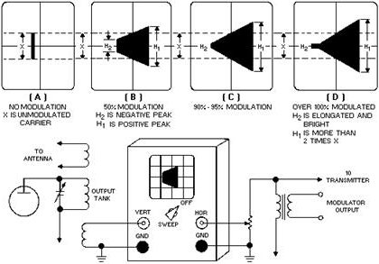
Amplitude-MODULATION MEASUREMENTS
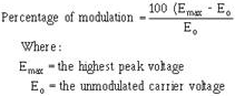
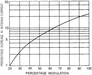
An increase in the power output of an AM transmitter is indicated by an increase in antenna current. The increase can be taken as a measure of the degree of modulation and can be expressed as a percentage, as shown in figure 5-1. The graph for this figure was developed from the relationship existing between the carrier power and the increased power resulting from the added modulation power. The formula for calculating the PERCENTAGE of MODULATION is as follows:
5-2
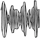
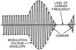
Figure 5-1. - Antenna current increase with amplitude modulation. The use of this formula is based on the assumption that the modulating voltage is a pure sine wave. Normal broadcasting, however, is characterized by complex envelope patterns, as illustrated in figure 5-2. In this light, the previous formula is not so clear. Consequently, the preceding formula should be viewed more correctly as the PERCENTAGE of Positive PEAK MODULATION. When the minimum voltage (E min) rather than the peak voltage (Emax) is used to compute percentage of modulation, the computed percentage (shown below) is the PERCENTAGE of Negative PEAK MODULATION:
5-3
Figure 5-2. - RF carrier amplitude-modulated by a complex wave envelope.
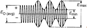
Since the preceding two modulation percentages often differ, you should define the AVERAGE PERCENTAGE of MODULATION, as shown below (refer to fig. 5-3):
Figure 5-3. - RF amplitude percentage modulation wave envelope.
From the preceding definitions of percentage of modulation, you should note that methods of measuring all three types of modulation percentages must be devised. When differing values are obtained, however, the cause may not necessarily be directly related to unequal positive and negative peaks of a complex modulation wave. Another possibility is distortion caused by carrier shift. Distortion may also be produced by effects other than the modulation process - for example, parasitic oscillation, nonlinear radio-frequency amplification of modulated signals, and distortion present in the audio amplifiers.
Unfortunately, continuous variations in the percentage of modulation create a number of additional problems. For example, damping is necessary so that a meter can provide an average reading despite fluctuations. An average reading, on the other hand, will not disclose the presence of transient overmodulation. This shortcoming is serious because of the large number of sideband frequencies produced in addition to the normal ones whenever overmodulation occurs. Not only do these extra frequencies interfere drastically with other transmissions, but they also may significantly distort the modulation signal. These considerations account for the importance of using a meter that responds to
5-4 modulation peak; specifically, both positive-peak and negative-peak overmodulation must be indicated. Positive-peak overmodulation occurs when the positive modulation exceeds 100%; negative-peak overmodulation occurs when the negative modulation exceeds 100%.
Oscilloscope Measurement Methods
The oscilloscope is widely used as an amplitude-modulation monitor and measuring instrument. Since it is capable of presenting visual indications of the modulated output of AM transmitters, the oscilloscope is reliable for detecting overmodulation and determining the percentage of modulation. For example, the relative error of most measurements taken with a 5-inch crt is about 10%. Although such accuracy is adequate for many maintenance checks, the oscilloscope is usually considered more valuable as a monitor of general modulation conditions. It is also used to monitor the amplitude-modulated output of a radio transmitter when photographic records are desired.
Types of Modulation Display
Two types of modulation patterns are provided by the oscilloscope, depending upon the hookup used. These patterns are the WAVE-ENVELOPE Patterns, as shown in figures 5-2 and 5-3, and the TRAPEZOIDAL Pattern, as shown in figure 5-4.
Figure 5-4. - Trapezoidal modulation patterns.
Figure 5-2 shows an oscilloscope presentation of an RF carrier that is amplitude-modulated by a complex wave, such as that of speech. Figures 5-4 and 5-5 show the effects of over 100% modulation on the carrier wave. The carrier wave envelope pattern (as shown in fig. 5-3) is obtained by applying the rf-
5-5 modulated wave to the vertical input of the oscilloscope. The trapezoidal pattern is obtained in a similar manner except that the modulation signal from the transmitter is used to horizontally sweep the oscilloscope (instead of having the sweep signal generated internally by the oscilloscope). Both methods are limited by the frequency response of the oscilloscope; therefore, these methods find greater applicability in the lf to HF ranges.
Figure 5-5. - Overmodulated RF carrier.
VHF and UHF MEASUREMENTS
In the vhf and uhf ranges, modulation is normally measured by applying a specific-level, 1-kilohertz tone to the input of the modulator. This, in turn, produces a significant drop in the plate voltage of the final output stage of the modulator. The correct setting of output plate voltage ensures that overmodulation will not occur.
Single-SIDEBand MEASUREMENTS
Single-sideband modulation is a form of amplitude modulation in which only one sideband is transmitted with a suppressed carrier. Since balanced modulators are used to provide carrier cancellation, the exact balancing of the carriers to provide cancellation requires a null adjustment. The null can be observed and adjusted by using either a detector and an indicator, such as a voltmeter, or an oscilloscope for observation of the output while tuning the transmitter.
Measurements peculiar to sideband technology also include special modulation-amplitude and modulation-distortion checks. If the sideband modulator is overdriven or mistuned or the associated linear amplifiers are improperly loaded or overdriven, spurious output frequencies are produced. These are harmonically related to the driving signals and can cause splatter over a large range of frequencies, thus causing interference to other transmitting stations.
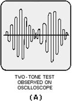
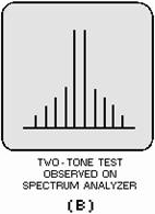
To determine the proper amplitude so that the modulation will not cause distortion or splatter, you use the audio two-tone modulation test. The resulting signals are shown in views A, B, and C of figure 5-6. The two-tone test is used for initial adjustment and for precise checking because it will indicate distortion. The two-tone test corresponds to the wave envelope method of AM modulation checking. Two signals of equal amplitude but of slightly different frequencies beating together are applied to the sideband modulator input to produce a single tone of approximately 1,000 hertz. On an oscilloscope, the
5-6 output appears as a series of fully modulated sine waves and is similar to a 100-percent-amplitude- modulated waveform, as shown in view A. a spectrum analyzer presentation is shown in view B.
Figure 5-6A. - Examples of ideal two-tone test waveforms.
Figure 5-6B. - Examples of ideal two-tone test waveforms.
5-7
Figure 5-6C. - Examples of ideal two-tone test waveforms.
When the trapezoidal method is used, two opposed triangles appear on the oscilloscope, as shown in figure 5-6, view C. When equally balanced modulators are used, the triangles are mirror images. Elliptical or straight-line patterns appear when the phase-distortion check is used.
It is also possible to make a rough operating adjustment by varying the audio drive from the microphone so that on peak swings a definite value of final plate current is not exceeded. This check depends upon the initial accuracy of calibration and response characteristics of the ammeter in the final stage, as well as other factors.
Frequency MODULATION
In frequency modulation, the carrier amplitude remains constant, and the output frequency of the transmitter is varied about the carrier (or mean) frequency at a rate corresponding to the audio frequencies. The extent to which the frequency changes in one direction from the unmodulated (carrier) frequency is called the Frequency DEVIATION.
Deviation in frequency is usually expressed in kilohertz. It is equal to the difference between the carrier frequency and either the highest or lowest frequency reached by the carrier in its excursions with modulation. There is no modulation percentage in the usual sense. With suitable circuit design, the frequency deviation may be made as large as desired without encountering any adverse effects that are equivalent to the overmodulation in amplitude-modulation transmissions. However, the maximum permissible frequency deviation is determined by the width of the band assigned for station operation.
In frequency modulation, the equivalent of 100% modulation occurs when the frequency deviation is equal to a predetermined maximum value. There are several methods of measuring the modulation in frequency-modulated transmissions.
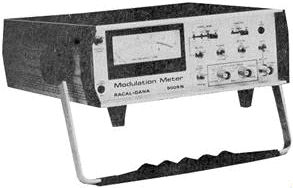
The frequency-deviation measurement of a frequency-modulated signal is normally performed with either a spectrum analyzer or with a modulation analyzer. The modulation analyzer method is more commonly used because of its accuracy. Typical accuracies for a modulation analyzer are within ±1%. Figure 5-7 shows a typical modulation analyzer.
5-8
Figure 5-7. - Typical modulation analyzer.
Q-3. What is meant by frequency deviation?
SPECTRUM WAVEforM ANALYSIs and MEASUREMENTS
An analysis of a complex waveform, prepared in terms of a graphic plot of the amplitude versus frequency, is known as SPECTRUM ANALYSIs. Spectrum analysis recognizes the fact that waveforms are composed of the summation of a group of sinusoidal waves, each of an exact frequency and all existing together simultaneously.
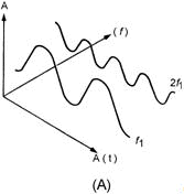
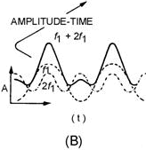
Three axes of degree (amplitude, time, and frequency) are important when considering varying frequency. The time-domain (amplitude versus time) plot is used to consider phase relationships and basic timing of the signal and is normally observed with an oscilloscope. The frequency-domain (amplitude versus frequency) plot is used to observe frequency response - the spectrum analyzer is used for this purpose. Figure 5-8 illustrates the differences between frequency- and time-domain plots. View a illustrates a three-dimensional coordinate of a fundamental frequency (f1) and its second harmonic (2f1) with respect to time, frequency, and amplitude. View B shows the time-domain display as it would be seen on an oscilloscope. The solid line, f1 + 2f1 is the actual display. The dashed lines, f and 2f1 are drawn to illustrate the fundamental and second harmonic frequency relationship used to formulate the composite signal f1 + 2f1. View C is the frequency-domain display as it would be seen on a spectrum analyzer. Note in view C that the components of the composite signal are clearly seen.
Q-4. a spectrum analyzer is designed to display what signal characteristic?
5-9
Figure 5-8A. - Time versus frequencies.
Figure 5-8B. - Time versus frequencies.
5-10
|
||||||||||||||||||||||||||||||||||||||||||||||||||