Quartz Crystal Resonators and Oscillators for Frequency Controland Timing Applications - A Tutorial March
2004 |
|
This document has been
release by the US Army Communications-Electronics Research, Development & Engineering Center for unlimited public
distribution. Unless otherwise noted, U.S. government documents are in the public domain.
Quartz Crystal Resonators and Oscillators for Frequency Control and Timing Applications - A Tutorial March 2004 John R. Vig US Army Communications-Electronics Research, Development & Engineering Center Fort Monmouth, NJ, USA J.Vig@IEEE.org
Rev. 8.5.1.2, by John R. Vig, July 2001, AD-M001251 Approved for public release. Distribution is unlimited NOTICES The findings in this report are not to be construed as an official Department of the Army position, unless so designated by other authorized documents. The citation of trade names and names of manufacturers in this report is not to be construed as official Government endorsement or consent or approval of commercial products or services referenced herein. Table of Contents Preface…………………………………………………………………………………v 1. Applications and Requirements………………………………………1 2. Quartz Crystal Oscillators………………………………………………2 3. Quartz Crystal Resonators……………………………………………3 4. Oscillator Stability……………………………………………………………4 5. Quartz Material Properties……………………………………………5 6. Atomic Frequency Standards…………………………………………6 7. Oscillator Comparison and Specification………………………7 8. Time and Timekeeping……………………………………………………8 9. Related Devices and Applications…………………………………9 10. FCS Proceedings Ordering, Website, and Index…………10
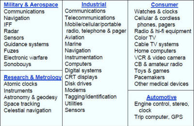
Preface Why This Tutorial? “Everything should be made as simple as possible - but not simpler,” said Einstein. The main goal of this “tutorial” is to assist with presenting the most frequently encountered concepts in frequency control and timing, as simply as possible. I have often been called upon to brief visitors, management, and potential users of precision oscillators, and have also been invited to present seminars, tutorials, and review papers before university, IEEE, and other professional groups. In the beginning, I spent a great deal of time preparing these presentations. Much of the time was spent on preparing the slides. As I accumulated more and more slides, it became easier and easier to prepare successive presentations. I was frequently asked for “hard-copies” of the slides, so I started organizing, adding some text, and filling the gaps in the slide collection. As the collection grew, I began receiving favorable comments and requests for additional copies. Apparently, others, too, found this collection to be useful. Eventually, I assembled this document, the “Tutorial”. This is a work in progress. I plan to include new material, including additional notes. Comments, corrections, and suggestions for future revisions will be welcome. John R. Vig CHAPTER 1 Applications and Requirements Quartz for the National Defense Stockpile, Report of the Committee on Cultured Quartz for the National Defense Stockpile, National Materials Advisory Board Commission on Engineering and Technical Systems, National Research Council, NMAB-424, National Academy Press, Washington, D.C., 1985. Electronics Applications of Quartz Crystals
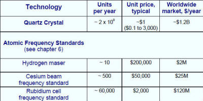
Quartz for the National Defense Stockpile, Report of the Committee on Cultured Quartz for the National Defense Stockpile, National Materials Advisory Board Commission on Engineering and Technical Systems, National Research Council, NMAB-424, National Academy Press, Washington, D.C., 1985. Frequency Control Device Market (as of ~2001) The units per year are estimates based on informal surveys of industry leaders. The numbers are probably accurate to better than a factor of two. Navigation Precise time is essential to precise navigation. Historically, navigation has been a principal motivator in man's search for better clocks. Even in ancient times, one could measure latitude by observing the stars' positions. However, to determine longitude, the problem became one of timing. Since the earth makes one revolution in 24 hours, one can determine longitude form the time difference between local time (which was determined from the sun's position) and the time at the Greenwich meridian (which was determined by a clock): Longitude in degrees = (360 degrees/24 hours) x t in hours. In 1714, the British government offered a reward of 20,000 pounds to the first person to produce a clock that allowed the determination of a ship's longitude to 30 nautical miles at the end of a six week voyage (i.e., a clock accuracy of three seconds per day). The Englishman John Harrison won the competition in 1735 for his chronometer invention. Today's electronic navigation systems still require ever greater accuracies. As electromagnetic waves travel 300 meters per microsecond, e.g., if a vessel's timing was in error by one millisecond, a navigational error of 300 kilometers would result. In the Global Positioning System (GPS), atomic clocks in the satellites and quartz oscillators in the receivers provide nanosecond-level accuracies. The resulting (worldwide) navigational accuracies are about ten meters (see chapter 8 for further details about GPS). Dava Sobel, Longitude, Walker & Co., New York, 1995
Commercial Two-way Radio Historically, as the number of users of commercial two-way radios have grown, channel spacings have been narrowed, and higher frequency spectra have had to be allocated to accommodate the demand. Narrower channel spacings and higher operating frequencies necessitate tighter frequency tolerances for both the transmitters and the receivers. In 1940, when only a few thousand commercial broadcast transmitters were in use, a 500 ppm tolerance was adequate. Today, the oscillators in the many millions of cellular telephones (which operate at frequency bands above 800 MHz) must maintain a frequency tolerance of 2.5 ppm and better. The 896-901 MHz and 935-940 MHz mobile radio bands require frequency tolerances of 0.1 ppm at the base station and 1.5 ppm at the mobile station. The need to accommodate more users will continue to require higher and higher frequency accuracies. For example, a NASA concept for a personal satellite communication system would use walkie-talkie-like hand-held terminals, a 30 GHz uplink, a 20 GHz downlink, and a 10 kHz channel spacing. The terminals' frequency accuracy requirement is a few parts in 10^8. R. Kinsman and D. Gunn, "Frequency Control Requirements for 800 MHz Land Mobile Communication," Proc. 35th Ann. Symp. Frequency Control, pp. 501-510, 1981.
Digital Processing of Analog Signals The Effect of Timing Jitter As microprocessor and digital signal processing (DSP) chips become more and more capable, the digital processing of analog signals, as illustrated in (A) above, becomes more and more advantageous and feasible. Among the advantages of digital (vs. analog) processing are that, in digital systems, many functions may be integrated on a chip (e.g., filtering, differentiation, integration, linearization, modulation, and computation), systems can be easily and inexpensively duplicated and reprogrammed, and systems do not depend on strict component tolerances. Before an analog signal can processed, however, the signal must be converted into digital form. An analog-to-digital (A/D) converter (also abbreviated ADC) samples the analog signal at (usually) equal intervals of time, and converts the analog signal into a sequence of digitized values (i.e., the analog signal is sampled, measured, then converted into quantized numerical values), as illustrated in (B) above. One of the sources of error in ADCs is jitter, i.e., the uncertainty in the time the signal was sampled. As shown in (C), an error Δt in the time of the sampling causes an error ΔV in the measured value of the signal. The higher the resolution (number of bits) and the speed of the ADC, the smaller the allowable jitter. At GHz frequencies, some 16 bit ADC clock jitter requirements are a few femtoseconds. Phase noise of the oscillator that drives the clock is one of the sources of timing jitter. The oscillator's contribution to jitter is the integral of the phase noise, L(f), usually from 10 Hz to ~30 MHz. J. A. Wepman, “Analog-to-Digital Converters and Their Applications in Radio Receivers,” IEEE Communications Magazine, pp. 39-45, May 1995. R. J. Lackey and D. W Upmal, “Speakeasy: The Military Software Radio,” IEEE Communications Magazine, pp. 56-61, May 1995.
Digital Network Synchronization • Synchronization plays a critical role in digital telecommunication systems. It ensures that information transfer is performed with minimal buffer overflow or underflow events, i.e., with an acceptable level of "slips." Slips cause problems, e.g., missing lines in FAX transmission, clicks in voice transmission, loss of encryption key in secure voice transmission, and data retransmission. • In AT&T's network, for example, timing is distributed down a hierarchy of nodes. A timing source-receiver relationship is established between pairs of nodes containing clocks. The clocks are of four types, in four "stratum levels." J. E. Abate, E. W. Butterline, R. A. Carley, P. Greendyk, A. M. Montenegro, C. D. Near, S. H. Richman, and G. P. Zampetti, AT&T's New Approach to the Synchronization of Telecommunication Networks," IEEE Communications Magazine, pp. 35-45, April 1989. J. Pan, "Present and Future of Synchronization in the US Telephone Network," IEEE Transactions on Ultrasonics, Ferroelectrics, and Frequency Control, Vol. UFFC-34, No. 6, pp. 629-638, November 1987. P. Kartaschoff, “Synchronization in Digital Communications networks,” Proc. IEEE, vol. 79, pp. 906- 914, 1991.
Phase Noise in PLL and PSK Systems The phase noise of oscillators can lead to erroneous detection of phase transitions, i.e., to bit errors, when phase shift keyed (PSK) digital modulation is used. In digital communications, for example, where 8-phase PSK is used, the maximum phase tolerance is ±22.5°, of which ±7.5° is the typical allowable carrier noise contribution. Due to the statistical nature of phase deviations, if the RMS phase deviation is 1.5°, for example, the probability of exceeding the ±7.5° phase deviation is 6 X 10^-7, which can result in a bit error rate that is significant in some applications. Shock and vibration can produce large phase deviations even in "low noise" oscillators. Moreover, when the frequency of an oscillator is multiplied by N, the phase deviations are also multiplied by N. For example, a phase deviation of 10^-3 radian at 10 MHz becomes 1 radian at 10 GHz. Such large phase excursions can be catastrophic to the performance of systems, e.g., of those which rely on phase locked loops (PLL) or phase shift keying (PSK). Low noise, acceleration insensitive oscillators are essential in such applications. See the acceleration effects section in chapter 4 for further information about acceleration induced noise and phase excursions. J. E. Abate, E. W. Butterline, R. A. Carley, P. Greendyk, A. M. Montenegro, C. D. Near, S. H. Richman, and G. P. Zampetti, AT&T's New Approach to the Synchronization of Telecommunication Networks," IEEE Communications Magazine, pp. 35-45, April 1989. J. Pan, "Present and Future of Synchronization in the US Telephone Network," IEEE Transactions on Ultrasonics, Ferroelectrics, and Frequency Control, Vol. UFFC-34, No. 6, pp. 629-638, November 1987. P. Kartaschoff, “Synchronization in Digital Communications networks,” Proc. IEEE, vol. 79, pp. 906- 914, 1991.
Posted 5/6/2011 |