|
October 18, 1965 Electronics
") [Table of Contents] [Table of Contents]
Wax nostalgic about and learn from the history of early electronics.
See articles from Electronics,
published 1930 - 1988. All copyrights hereby acknowledged.
|
"Xeledop" is the Word of the
Day for October 6; use it often. Xeledop is an acronym for "transmitting elementary
dipole with optional polarity." Nope, I've never heard of it, either. The Xeledop
(probably pronounced "zeh'-le-dop") is an air-towed transmitter that flies a pre-planned
path around the ground-based antenna under test (AUT) whose radiation pattern is
being measured. The circular power level plot at the bottom of the page shows the
results of an actual test flight. In this application, a high frequency (HF, 3-30 MHz)
transmitter is towed behind an airplane like target drone while it broadcasts signals
at eight distinct frequencies toward the AUT, while the downstream receiver records
power levels. The pilot flies on the surface of an imaginary hemisphere to maintain
a constant radius from the antenna. Ground equipment tracks the aircraft azimuth
and slant range is calculated using aircraft altimeter data and measured elevation
angles. Both horizontal and vertical radiation patterns can be measured. A VHF model
was also tested.
This is somewhat similar to the
Drone-Based Field Measurement System™ (dB-FMS)™ that I proposed
back in 2014. My scheme uses a remote controlled drone with onboard measurement
receiver and GPS to fly a programmable profile for determining the radiation pattern
of a ground-based transmitter - basically the opposite of the Xeledop system. Since
antennas are reciprocal devices, the measured radiation pattern of a transmitter
is equivalent to that of a receiver using the same antenna, and vice versa. I hope
to achieve millionaire status some day when someone pays royalties for commercializing
my idea ;-)
If you have a subscription to the IEEE Library, check out "Measurement and
Modelling of HF Antenna Gain and Phase Patterns and the Effect on Array Performance,"
by R.W. Jenkins and L.E. Petrie. It is a modernized Xeledop measurement method that
uses differential GPS for a precise tow aircraft position.
Transmitters Towed Through Air Tests Antenna's Radiation Pattern
 Signals transmitted by airborne equipment are
measured at the antenna to obtain accurate measurements at high and very-high frequencies Signals transmitted by airborne equipment are
measured at the antenna to obtain accurate measurements at high and very-high frequencies
By Cecil Barnes Jr.,
Stanford Research Institute, Menlo Park, Calif.
In theory, the radiation pattern of extremely large antennas can be calculated.
In practice however, it is not always possible because the pattern is affected by
local topography, conductivity of the soil, and by reflections from other antennas,
power lines, or metal structures in the area. Because of all these factors, methods
of checking are needed to determine whether existing antennas meet directional requirements.
One cannot complacently assume that the calculated values will give the correct
radiation pattern of an antenna constructed in the field.
Modeling techniques are impractical because the conductivity of the antenna cannot
be scaled and the ground constants are often unknown. The only sure way to determine
the pattern of a large antenna is by direct measurement.
Towing the Transmitter

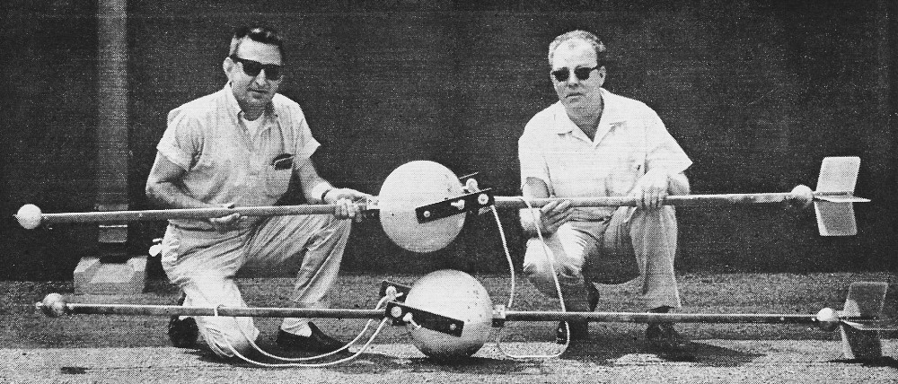
High-frequency Xeledop, equipped with fins for horizontal polarization,
assembled and ready to be loaded on plane. Second Xeledop is kept in plane as spare.
Only one unit can be flown at a time.
One way of getting direct measurements is to fly around the antenna as a signal
is transmitted from the aircraft and to record the reception of the signal by the
antenna. A plot of the voltage measured at the antenna terminals as a function of
aircraft position will give the radiation pattern. The airborne technique covers
angles above the horizon, and is considerably faster and more accurate than either
walking or riding around an antenna while it is transmitting, and measuring the
pattern with a field-strength meter.
Simple as the measurement from an airplane sounds, many complications arise.
One, in particular, is that at high frequencies (3 to 30 Mc) some part of the airframe
may be resonant and introduce an error in the results by reradiating additional
signals. For this reason, when testing high-frequency antennas from the air, it
is necessary to place the transmitter in an aerodynamically stable housing and tow
it at a distance that makes re-radiation negligible.
The latest transmitter designed for towing by aircraft is called the Xeledop,
an acronym for transmitting elementary dipole with optional polarity. Eight transmitters
in the Xeledop can broadcast at eight different frequencies. These frequencies are
selected to cover the antenna's complete bandwidth. One Xeledop can be used to test
several antennas simultaneously. To measure the polarization characteristics of
the receiving antenna, the Xeledop can be easily oriented in either a horizontal
or vertical position.
The Xeledop system is an improvement over the pioneering techniques previously
used [Electronics; Nov., 1955, pp. 134-136]. The advent of transistors has eliminated
tube filaments and consequent battery drain, allowing operation of several transmitters
over many hours. When oriented vertically, the Xeledop remains vertical regardless
of air speed. Today, the pilot has a constant-distance indicator to assist him in
maintaining a constant radius around the antenna being tested. And data processing
is speeded with the aid of computer techniques.
Xeledop Design
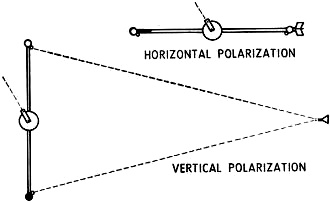
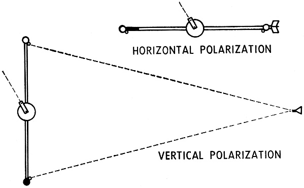
Glass fiber fins on one radiator and an iron counterweight on
the other keep the Xeledop horizontal when towed, as shown in the top diagram. For
vertical polarization, the fins and counterweight are removed and a lead weight
is substituted for one of the hollow balls. The bottom diagram shows how the drag
cone is deployed to aid in keeping the Xeledop vertical as it is towed.
Two different Xeledops are used for high and very-high frequencies. The h-f Xeledop
is a glass fiber sphere approximately 11 inches in diameter, from which extend two
streamlined 44-inch radiators. Each radiator terminates in a 3-inch-diameter hollow
metal ball. The h-f Xeledop is normally towed 300 feet behind a fixed-wing aircraft,
traveling at speeds between 100 and 170 miles per hour, on a single 3/16-inch-diameter
line of braided nylon with a breaking strength of 1,000 pounds. The line is attached
to the Xeledop with a Dacron bridle and a non-conducting phenolic handle pivoting
on an axle extending through the center of the sphere.
To make the Xeledop assume a fore-and-aft horizontal position and thus radiate
horizontally polarized signals, glass fiber fins are attached to the end of one
radiator and counterbalanced by a small weight inside the other.
To achieve vertical polarization, the fins and forward counterweight are removed
and a 5 1/2-pound lead ball is substituted for one of the hollow balls. A drag cone
is added to prevent pitching. In this way, the center of pressure (from the slip
stream) lies on the axle; the center of gravity lies below it.
The third direction of polarization is horizontal with the dipole axis at right
angles to the line of flight. For this, a helicopter is used, flying at slow speed
with two separate tow ropes attached from the ends of the Xeledop dipole to two
support points on the helicopter; in this case the drag cone is used to prevent
yawing.
The length-to-width ratio of the radiators, the diameter of the small top-loading
balls, and the shape of the main housing (spherical) are chosen so that the assembly
will function electrically and at the same time be aerodynamically stable whether
vertical or horizontal. The batteries and other components inside the sphere are
placed so their center of gravity is at the center of the sphere. Flight tests with
an airplane have shown that the Xeledop is stable in the first two configurations
between 40 and 250 mph, it is not stable below 40 mph, and it has not been tested
above 250 mph. The changes required to switch from one polarization to the other
do not detune the antenna system or affect the radiated power because no conducting
parts are affected.
The vhf Xeledop is similar to the h-f model except that the sphere is nine inches
in diameter and the radiating elements are a half-wavelength long at the highest
frequency. Glass fiber extension rods hold fins and weights, as needed, 16 inches
away from radiating elements to avoid electrical interaction. When flying vertically,
a lead weight is carried 16 inches below the bottom radiator and a balsa-wood ball
of equal drag, is mounted 16 inches above the top radiator.
Dipole and Bandwidth
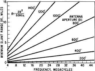
Minimum distance from the antenna to Xeledop, based on the highest
Xeledop frequency to be used, is plotted for different antenna apertures, largest
antenna dimension or distance between nearby reflecting objects.
The Xeledops must be designed to simulate elementary (or short) dipoles so that
their radiation pattern will be known. This means that the total length of the radiators
cannot exceed one-half wavelength. However, short elements have low radiation resistance;
if the elements are too short, it becomes difficult to match the transmitter output
to the dipoles without excessive losses in the matching network. On the other hand,
if the elements are too long, the dipole cannot be considered "elementary," and
it will not have the desired radiation pattern. The dipole dimensions govern the
bandwidth over which the Xeledop operates.
The configuration of the h-f Xeledop allows op-eration at frequencies as high
as 50 Mc before the pattern is distorted. Operation at frequencies as low as 2 Mc
is achieved by top loading each ele-ment with the 3-inch metal ball and by suitable
choice of high-Q circuit components in the dipole matching networks. Each transmitter
is matched to the dipole through a balanced ceramic-ferrite toroidal transformer
using different materials for frequencies below and above 20 Me,
The h-f Xeledop can transmit pulses sequen-tially on eight crystal-controlled
frequencies in the 2-to-50-Mc band. The pulse width depends on the cycling rate.
This is set to give the desired sam-pling rate for one frequency, and is governed
by the detail of the pattern to be studied and the speed of the airplane, normally
about half a degree of azimuth per second.
Stepping Switch
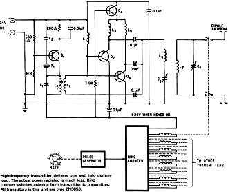
High-frequency transmitter delivers one watt into dummy load.
The actual power radiated is much less. Ring counter switches antenna from transmitter
to transmitter. All transistors in this unit are type 2N3053.
An electronic stepping switch is used to key each transmitter sequentially and
connect it to the dipole. The stepping switch, or keyer, consists of a free-running
pulse generator which drives a 9-stage ring counter using silicon-controlled switches.
The first ring counter stage generates a quiet pulse period for timing and other
operations in an automatic recording system. Each subsequent stage drives an antenna
switching relay and keying circuit for its associated transmitter unit. The frequency
of the pulse generator is variable from 2.5 to 40 cycles per second; each pulse
from the generator causes the ring counter to step ahead, keying a transmitter,
releasing one relay, and closing the next so that one transmitter at a time is turned
on and connected to the antenna. The ring counter may be adjusted to bypass one
or more stages; thus the Xeledop can cycle at a steady pulse rate (5-millisecond
interval between pulses) on any number of transmitters from two to eight, or it
can transmit continuously on one frequency. Pulses transmitted are the same width
and unmodulated.
The vhf Xeledop was designed to transmit on three frequencies. The keyer is similar
to the h-f unit except a four-stage transistor ring counter is used, and the need
for antenna switching relays is eliminated by a passive multi coupler.
Positioning the Xeledop
When he's ready to take the Xeledop aloft, the pilot takes along aerial photographs
or topographic maps of the area with a flight-path circle drawn around the antenna.
At low altitudes this circle is a guide enabling him to fly the airplane on an accurate
track. At high altitudes or when flying over water or above clouds, the pilot is
guided by a zero-center milliammeter mounted on the instrument panel. This meter,
known as a deviation indicator, is driven by an interrogator, operating with a transponder
at the antenna. The meter, similar to an instrument-landing system indicator, shows
the pilot his deviation from the desired circular path and gives him right-left
steering indications.
Lines on the face of the meter represent deviations of approximately one-tenth
mile off the circular course. The deviation indicator is initially set with reference
to the ground. When over a landmark on the flight circle at a specified altitude,
the pilot sets the indicator to zero and locks the control. The pilot may deviate
appreciably from the flight track without introducing serious error in the results.
A 10% change in the distance between the airplane and the antennas causes less than
1 decibel change in the signal level. In any event, changes in range are allowed
for in the data reduction.
Orbiting a Hemisphere
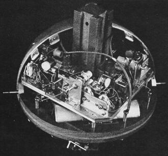
With the cover removed, three of the Xeledop's transmitters can
be seen. One of the nickel-cadmium batteries is visible below the transmitters.
To conduct the pattern measurements at elevation angles below 45°, the pilot
flies over the surface of an imaginary hemisphere, keeping his radius constant during
each orbit by means of the deviation indicator. He covers the surface of the hemisphere
in steps, usually from 3° above the horizon to 45°, maintaining a constant
altitude during each orbit plus a 30° overlap for a validity check. Seven to
ten orbits are usually required to get satisfactory coverage for an antenna pattern;
one orbit is chosen to take the Xeledop through the antenna's estimated main beam.
Calibration of the ground equipment is repeated while the pilot is changing altitude.
The radius at which the airplane is flown depends on the frequency of the test
signal and on the size of the antenna to be measured. In some cases; it is limited
by the airplane's ceiling. According to a rule of thumb commonly applied to pattern
measurements, the aircraft should be far enough from the antenna to satisfy the
equation:
R = (2D2)/λ
where R = slant range from antenna to aircraft, D = diameter of antenna aperture, λ
= wavelength of highest Xeledop frequency.
The term D may represent simply the largest over-all dimension of the ground
antenna includ-ing its ground plane, if any; or it may be the largest dimension
of a complex installation of many antennas if reflections from other antennas and
guy wires are to be considered. In most cases, a radius of 3 to 5 miles is satisfactory.
The minimum slant range at which the airplane should fly for various frequencies
and antenna apertures is indicated in the graph on page 98. Even so, bringing the
airplane in to one-half this distance introduces an error of only a few percent
in the measured antenna gain.
Circle or Grid
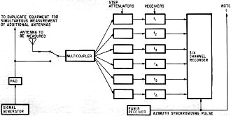
Ground equipment necessary to test one antenna at six frequencies.
Adjacent antennas can be measured simultaneously. A Rawin receiver (radar used to
measure wind velocity and direction) tracks the airplane, in azimuth and elevation,
and supplies the pulse to the recorder for coordinating received signals with plane
position.
Experience has shown that a pilot can fly a fixed-wing aircraft above a cloud
layer on a constant radius of 4 to 10 miles with the deviation indicator as his
only guide at angles up to 45° above the horizon. At higher angles, the indicator
becomes difficult to follow and accuracy drops.
For elevation angles above 45°, therefore, the airplane flies a rectangular
grid pattern at a constant altitude over the antenna site, with the ground equipment
tracking it on each pass. To fly this pattern, the pilot must have a clear view
of the ground unless some rather exotic navigational equipment is on board. If the
Xeledop is horizontally polarized, the pilot reports his heading, and consequently
the direction of the dipole axis, on each pass. Because of cross winds, these headings
may not coincide with the grid tracks; this conflicting data is later corrected
by a computer.
The azimuth and elevation of the aircraft is determined by automatic ground radio
tracking equipment. The slant distance to the aircraft is calculated from the measured
elevation angle above the horizon and the altitude reported by the pilot.
On circular flights, the airplane can complete about three orbits per hour depending
upon radius, including climbing and descending, or three hours to complete data-taking
below 45° at one polarization. A grid pattern takes six hours.
Getting the Information
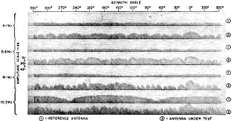
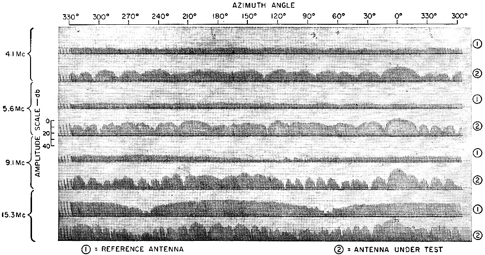
Typical chart recording of the signals received at the ground
station clearly show the lobe structure at four different frequencies. Each spike
on the recording represents one pulse from the Xeledop. It is clear from the plot,
second from bottom, that the reference antenna had two nulls, 180° apart, at
15.3 megacycles.
The recorder input signals are the automatic gain control supply voltages of
the receivers. The gains are set so that 40 decibels occupy the width of one channel.
Attenuators handle signal variations in excess of 40 db by adding or subtracting
attenuation in 10-db steps. Analog-type recording has been used so far, with recorders
designed so that the operator can continuously monitor the recorded information
and immediately detect any malfunction. Since high-frequency response is not required,
a multichannel paper-strip recorder is satisfactory, producing a clear, easily interpreted
record. The figure on page 101 shows a sample record of four frequencies recorded
as the aircraft made an orbit around a pair of antennas. The pilot flew more than
360° in azimuth to create an overlap, thus providing one method of checking
the results. Each spike on the record represents a pulse transmitted from the Xeledop.
The space between pulses shows the noise level on each channel, indicating the signal-to-noise
ratio; in this example, however, the noise on all the channels is below the threshold
set for the test. The height of the pulses represents signal strength. The lobe
structure of the antennas being tested is clearly visible. A rectangular waveform
made by the marker pen along the top edge of the chart provides a synchronizing
signal for comparison with the separately recorded plane position.
The first step in the data reduction process, a screening process, consists of
a visual inspection of the strip charts and field notes. During this inspection,
the data for further analysis is selected and the azimuth synchronizing-pulse correlation
numbers are written on the charts. Next, the analog information from the strip charts
is transferred to punch cards along with data relating to the antenna, frequencies
used, aircraft altitude, Xeledop polarization, nominal slant range, date and test
number. On each card is entered the appropriate synch-pulse number and an amplitude
for each channel of interest. Readings are taken for every 5° of azimuth and
at all points of maximum or minimum recordings.
The azimuth-elevation information from the ground tracking equipment is punched
into a second set of cards from a record, which is printed at six-second intervals,
showing azimuth angle, elevation angle, and a synch-pulse number. This completes
the manual processing of the data.
The two sets of punched cards are fed into a digital computer which combines
the information on the input cards and incorporates corrections for the following:
parallax due to the distance between the antenna and tracking equipment, change
of slant range when flying a grid pattern or due to an eccentric or off-course orbit,
Xeledop antenna pattern, distance of Xeledop below and behind airplane, and a shift
of azimuth zero reference from true north to the nominal direction of the main beam.
In addition, the computer remembers the largest signals recorded; this information
is used later to normalize all signals of one frequency to zero decibels. This information
is also used to compare the gain of one antenna with another. The punched card output
of this computer is fed into another computer along with a program for drawing and
labeling contours.
Drawing the Pattern
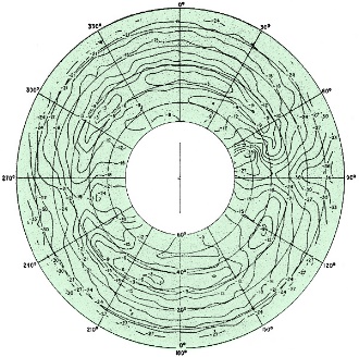
Contour lines, at 3·db intervals, are plotted by the computer
from information it has received from punch cards. This pattern is of a horizontal
dipole 2·feet·high and 78·feet·long. The signals were recorded at 10 Mc with the
Xeledop vertically polarized.
The magnetic-tape from the second computer is fed into an automatic plotting
machine which plots contour maps of the antenna patterns by drawing contour lines
for 3-db intervals and writing the decibels below the maximum reading at suitable
locations along the contour lines. The pen-recorder also makes several small registration
marks near the edge of the paper; these are later used as guides for photographically
superimposing a polar grid. In the process of computing the contour-line locations,
the computer interpolates between measured values and thus is able to establish
field-strength levels at locations between orbits where the airplane did not fly,
It is because of this capability that the aircraft need not fly a perfect grid or
a perfect orbit around every antenna.
A T-11 Beechcraft and a modified B-25 bomber have been used satisfactorily for
pattern-measurement. The Xeledop is carried inside the airplane during takeoff and
landing and lowered through a hatch in the floor for use. Helicopters have been
used on special occasions where vertical descents or horizontal polarization at
right angles to the line of flight were required.
Statistical distribution of burst durations as measured on the Seattle-Bozeman
link. Curve is a plot of the measured probability of meteor bursts occurring whose
duration is greater than an arbitrary duration.
Measured statistical distribution of period between bursts.
Posted October 5, 2023
(updated from original
post on 10/31/2018)
|


")