|
February 14, 1964 Electronics
") [Table of Contents] [Table of Contents]
Wax nostalgic about and learn from the history of early electronics.
See articles from Electronics,
published 1930 - 1988. All copyrights hereby acknowledged.
|
I would love to see a modern electromagnetic
(EM) field software
simulation of this antenna design. Imagine attempting a ray-tracing model of the
symmetrical combination of multiple linear and circular radiating elements of the antenna
shown in this 1964 article that appeared in Electronics magazine. Doing so would
have required hours of expensive time on an
ENIAC or weeks from
a team of woman "computers" such as the kind NASA used for plotting Apollo trajectories
(see Hidden Figures). I'd like to see
Joel Hallas (W1ZR) model it in EZNEC. Supposedly, at least one working
WARLA (Wide
Aperture Radio Location Array) system was built and tested, but details of the results
are not provided (probably classified at the time).
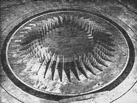
H-F Array Scans Horizon
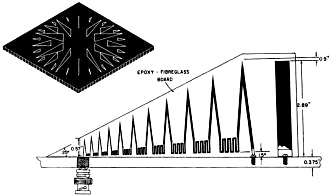
Three-band configuration is proposed for full-scale model (top). Meanders
are used instead of tuning stubs in printed-circuit elements
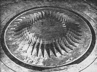
Antenna model operates at 1 to 3 Gc (GHz)
Big radiolocator could provide long-distance directional communications
Urbana, Ill. - University of Illinois' radiolocation lab is working on a new style
of directional antenna array - one that would use frequency-independent, log-periodic
elements. It could be used for directional long-distance transmission and reception.
Electronic scanning of 160 elements in a 1,000 to 2,000-foot-diameter array could
spin a fan-shaped beam, 1 to 30 degrees wide, around the horizon several times a minute,
Prof. Paul Mayes reported at the University's antenna forum two weeks ago.
The lab now operates a Wullenweber antenna. The new system, called WARLA (Wide Aperture
Radio Location Array) being developed by the University and Navy, would update that installation.
Where folded monopoles of the Wullenweber limit its operations to receiving, WARLA's
log-periodic elements could be used for transmitting in a global, point-to-point, military
communications network, according to John Greiser, of the lab. Frequency range of the
Wullenweber is 4 to 16 Mc. WARLA's is 2 to 32 Mc. Beam width would change from 30 degrees
to 1 deg, the beam's pointing accuracy from 1 degree to 1/4 deg, and gain from 35 db
to 20 db as transmitting frequency rises.
Transmitter powers could range upwards from 30 kw peak and 600 w average. By exploiting
skips from atmospheric layers, which could become double hops around 32 Mc, range could
be 2,000 to 3,000 miles.
The lab is now working with a scale model operating at 1 to 3 Gc, with elements reduced
500: 1 in size.
For a full-size antenna, a three-band configuration (sketch) could be used. At 2 to
5 Mc, 40 large elements would be activated, at 5 to 32 Mc, 40 intermediate elements would
go into operation, and at 12.5 to 32 Mc, a final set of 80 smallest elements could be
used. The number of elements may be reduced in the final design.
Posted September 27, 2018
|


")