|
February 28, 1964 Electronics
") [Table of Contents] [Table of Contents]
Wax nostalgic about and learn from the history of early electronics.
See articles from Electronics,
published 1930 - 1988. All copyrights hereby acknowledged.
|
Electronics
magazine is very different from all the other vintage electronics magazines I have used
in the past. Electronics is much more focused on military, space, and fundamental
research. New issues were published bi-weekly by McGraw-Hill from 1930 until
1988. About half the editions (this is not one of them) had two to three times as
many pages as the other half, with most of the extra pages being advertisements.
The publishers must have made a fortune on advertising revenue. My guess is that
the vast majority of the companies appearing in the early 1960s issues I bought
on eBay do not exist anymore, having either gone out of business or having been
acquired by bigger companies. If you were around in the era, you will probably see
every company you remember represented. The article presents a very interesting
antenna concept. Someone had his thinking cap on real tight when dreaming up the
radio wave focusing scheme described. A "high speed computer" was used for simulations
prior to building the prototype. Its key objective was to drastically reduce the
amount of acreage needed to obtain performance akin to rhombic layouts. The Federal
Aviation Administration (FAA) funded the project citing a need for reliably receiving
intercontinental air traffic control information. Readily available satellite communications
had not yet been established at the time - but very soon thereafter would be, which
is probably why we don't see much about this antenna today.
Lens-Like Antenna: Low Noise, Less Space

Comparison of wire-grid antenna and part of the 1,100-acre antenna
farm formerly required. Diamond patterns outlined by poles show individual rhombic
antennas.
By G. V. Rodgers, Chief, Data Transfer Section, Federal Aviation Agency, Washington
25, D. C.
Wire-grid array improves signal-to-noise ratio and gives excellent gain in any
direction. Erection space only 850 feet in diameter reduces cost
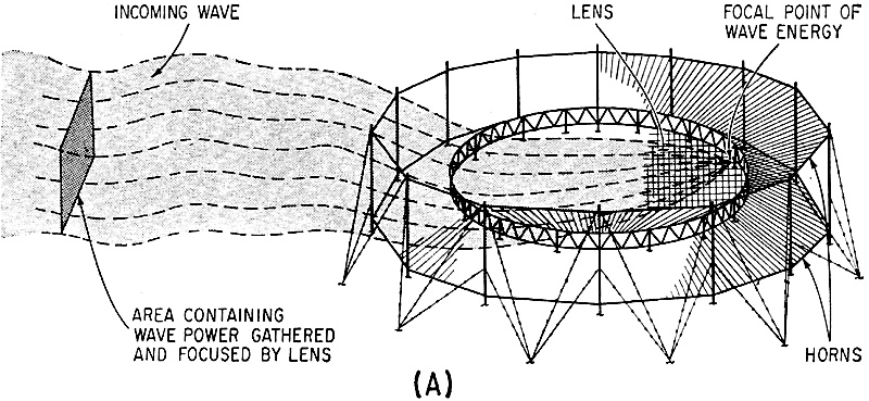
Radical departure from conventional antenna technology is demonstrated in the
design of a high-frequency lens antenna that consists of two circular grids, suspended
one over the other, and surrounded by a radial wire horn. Electromagnetic waves
are intercepted by the horn, concentrated in a vertical direction, and transferred
to the lens as depicted in Fig. 1.
Refraction within the lens causes the wave front to bend and converge at a focal
point on the diametrically-opposite side, where a transmission-line coupler is located.
Up to thirty-six couplers may be installed in the lens to provide coverage in as
many different directions. Outputs from the feeds can also be combined to provide
a steerable beam for full azimuthal coverage.
Developed for the Federal Aviation Agency by R. L. Tanner of TRG-West, the wire-grid
lens antenna is located at the International Flight Service Receiver Station on
the island of Molokai, Hawaii. Signals transmitted from Anchorage, San Francisco,
Sidney, Tokyo, and other Pacific Ocean points are received and relayed to the FAA
Air Traffic Control Center near Honolulu. Rhombics previously installed to receive
these transmissions require about 1,100-acres of land, whereas the lens requires
only 850 feet for simultaneous reception of signals over operational circuits from
seven directions between 3 Mc and 30 Mc. Poles that hold some of the rhombics, and
the wire-grid lens that is intended to replace them appear in the lead photo. The
line from the lens to the buildings contains feedlines.
Fig. 1A - Concentration of wave energy by wire-grid lens
shown in artist's drawing.
Design - Lens techniques, based upon optical theory developed
by the late R. K. Luneburg1 have been applied in the design of relatively
small microwave and UHF antennas. In these antennas, wave focusing is generally
accomplished with a dielectric foam material with a refractive index that is made
to vary over the cross section in a prescribed fashion. The Luneburg lens may be
constructed in spherical or disc form; the concept has not previously been extended
to the lower frequencies due to the impracticability of using solid dielectric materials
in large structures.
The wire-grid lens antenna2 has properties which resemble the disc-type
Luneburg lens. The solid dielectric is eliminated and the focusing properties of
the lens are achieved by varying the spacing between a pair of wire grids in a systematic
manner. Index of refraction is made to vary as a parabolic function across the lens
aperture, and the velocity of propagation varies between the free space value at
the circumference of the grids, to approximately 70% of the free-space value at
the center of the grids. This variation in velocity of propagation of a wave entering
the lens may be explained as follows.
Operation - At the edges of the lens where the spacing between
the grids is large relative to the mesh size, the grids simulate a pair of metal
plates and the wave in this region propagates at nearly the speed of light. At the
center of the lens, where the spacing between the grids is small compared to the
mesh size, the grids act as a network of interconnected open-wire transmission lines
and the wave in this region propagates at a slower rate, that has been shown2
to be 1/√2 times the velocity of light. The end result is that the plane wave
front intercepted by the lens is transformed into a curved wave front, with rays
converging at a focal point on the opposite side. The properties of the lens are
independent of frequency, as long as the mesh size is small compared to a wavelength,
at the highest operating frequency. Since the waves traveling between the grids
have electric fields that are generally vertical, the antenna is essentially vertically
polarized.

Fig. 1B - Transmission-line coupler assembly installed
in the lens.
Radiation efficiency at lower frequencies is preserved by the electromagnetic
horn attached to the grid. This horn provides proper impedance match between free
space and the lens, and also increases vertical directivity.
Construction - The wires that comprise the grids are attached
to rings fabricated from specially extruded aluminum sections. Both upper and lower
grids are identical; each of the rings is 600 ft. in diameter with grid wires spaced
to form squares 5 ft. on a side. The mesh is uniform from the center of the lens
to a distance of 37-1/2 ft. from the outer edge, where satellite wires taper away
from each of the major grid wires to form a mesh of 2-1/2 ft. squares at the periphery
of the lens.
The two grid rings are attached together by diagonal-web members of impregnated
hardwood to form a truss. The spacing between the upper and lower grids is 12 ft.
at the rings and 6-1/2 inches at the center of the lens. Proper spacing between
the grids is maintained by insulating spacers.
The horn is composed of wires which extend radially from the lens rings to bridle
cables attached to the 24 outer poles, which average 94 ft. in height. There are
504 radial wires, 145 ft. long in the upper-horn curtain and an equal number of
wires, 130 ft. long in the lower curtain. Short lengths of wire are connected between
the radial wires out to 1/5 of their length from the lens rings. These wires are
necessary to provide paths for circumferential currents produced by the higher order
propagation modes which would otherwise be strongly excited, due to the discontinuity,
and contribute to side and back lobe radiation.
The upper-horn curtain is attached to the outer poles at points which are a constant
height above the plane of the lens. The lower-horn curtain is attached to the poles
at points seven feet above the ground. The average angle between the horn curtains
is 25 degrees.
Line Coupler - The device used to couple the signal from the
lens to the receiver transmission line, is a modified ramp feed that evolved from
a comprehensive series of experiments and calculations. In simplified form, the
ramp feed consists essentially of one or more conductors extending diagonally between
the lower and upper grids of the lens. Since the ramp has vertical current components
along its slope, it may be considered as a series of vertical current elements which
couple to the electric fields of the waves traveling between the grids. The array
pattern is a cardioid with its null in the rearward direction.
The antenna described in this article uses lens techniques based upon optical
theory developed by the late R. K. Luneburg. While the Luneburg lens has been used
extensively at microwave frequencies, this array is the first to extend lens principals
to the 3-Mc to 30-Mc range. Moreover, the antenna described does the job formerly
assigned to 1,100 acres worth of rhombics, yet requires only a fraction of the geographical
area necessary for rhombics with equivalent coverage.
The actual feeds extend 75ft. into the lens as shown in Fig. 1B. Each feed
consists of a pair of wires spread apart along their lengths to provide a constant
impedance. Maximum coupling between the lens and the feed occurs when the phase
velocity along the feed is slightly slower than that of the lens. This wave slowing
was accomplished by the addition of capacitive loading in the form of aluminum plates
connected across the wires of the ramp. The phase velocity along the feed is slowed
from the free space velocity by the ratio of 1.2:1. Broad banding of the feed is
accomplished with a constant-resistance network in which R = √L/C. The current
in the end elements is fed in the proper phase relationship with respect to the
ramp through phase-inverting transformers connected to each of the current elements.
The coupler is constructed with two identical feeds spaced 30-ft. apart at the
circumference of the lens. The pattern characteristics of the feed are such that
less of the lens aperture is illuminated at the higher frequencies, making beam
width essentially constant at frequencies above 10 Mc.
Performance - Results of preliminary tests indicate that the
antenna is performing in accordance with design predictions. Impedance match to
the transmission line surpassed expectations; the highest standing wave ratio measured
for any of the couplers over the entire frequency band is less than 2:1 at the antenna
coupler output. The beams are well defined with a minimum of side and back lobe
radiation.
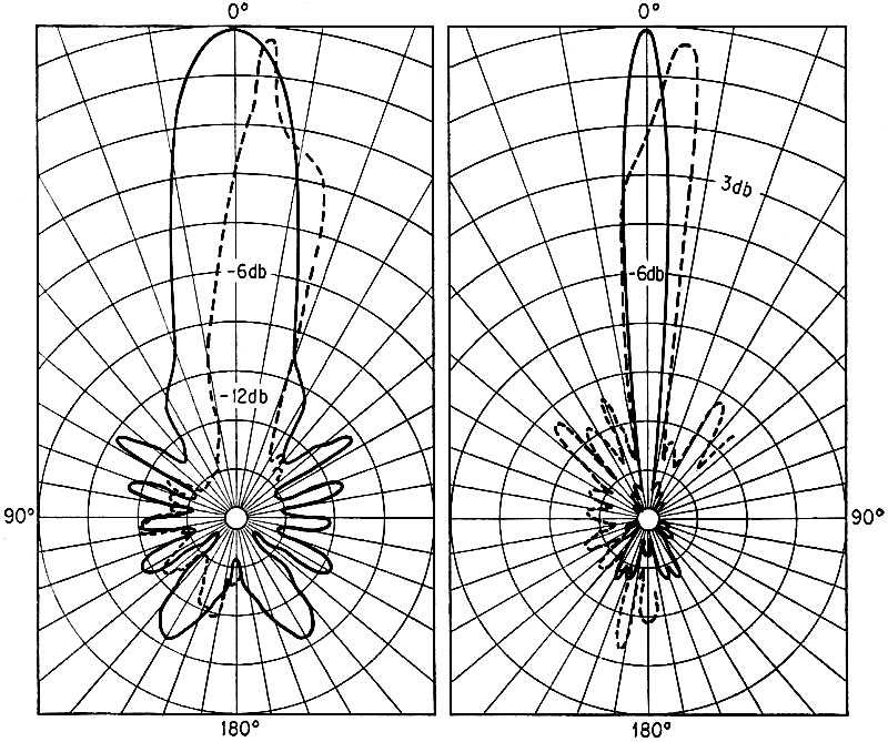
Fig. 2 - Polar patterns showing calculated (solid) and measured
(broken) plots of the array. Patterns were calculated for 4.0 Mc and 30 Mc, while
measurements were taken at 3.8 Mc and 25 Mc.
Throughout the development cycle, two valuable tools were employed to optimize
design parameters. The first was a 1/ 40th scale model of the lens and horn structure,
and the second, a high-speed digital computer equipped with an automatic pattern
plotter. Analytical methods were used to derive the differential equations describing
wave propagation in the lens and the feeds. These equations were solved directly
by the computer, while the scale model was used for experimentation to improve the
feed and coupling methods. A complete set of calculated patterns was produced by
the computer. Example of calculated patterns for frequencies near both ends of the
band are shown in the solid curves of Fig.2.
As generally recognized, it is extremely difficult to obtain full-scale radiation
patterns of antennas operating in the HF range. This being the case, the results
of calculations or measurements using scale models, are usually accepted as final
results. Since there is such widespread interest in application of the wire-grid
lens to communications and other purposes, full-scale pattern measurements are mandatory.
As an initial approach to this objective, a set of patterns measurements was made
with a test transmitter and antenna mounted on a vehicle.
The receiver site on Molokai was surrounded by a network of roads, making it
possible to define a path sufficiently distant from the antenna to be in the far
field of radiation. A total of 43 test stations were established along this path
and their azimuthal directions from the antenna were defined with reasonable precision.
By moving the vehicle from one test station to another, it was possible to define
the main beam of one feed and the side and back lobe radiation from another. The
results were pieced together to form fairly complete patterns. Examples of the actual
patterns obtained by this method are shown in the broken curves of Fig. 2.
Irregularities in measured radiation patterns are attributable to two causes.
First, the contours of the terrain on the island and the geography of the roads
available for running the vehicle containing the test transmitter were such that
it was impossible to obtain line-of-sight measurements. The patterns taken, therefore,
represented signal fringing over the edge of hills between the antenna and the transmitter.
Second, the antenna used as a reference was found to be far from omni-directional.
Actually, two antennas were used for this purpose; a tuned whip with the grids of
the lens acting as a counter poise, and a huge bi-conical composed of the upper
and lower lens and horn segments. Neither of these reference antennas was omni-directional,
but it appeared from the data that the bi-conical feed to the lens provided the
most uniform reference. This antenna was used to plot the data shown in Fig. 2.
Preliminary operational tests of the lens antenna compared to the rhombics indicate
that although the signal level received via the lens was lower than that received
from the rhombics, the improved signal-to-noise ratio resulted in increased readability
at lower signal levels.
The Federal Aviation Agency is preparing for a comprehensive evaluation of the
wire-grid lens antenna with support from the U. S. Army Electronic Research and
Development Laboratory at Fort Monmouth and the U. S. Navy. This program, will include
flight-test measurements of the full-scale radiation patterns and operational tests
to determine performance.
Posted October 19, 2023
(updated from original
post on 7/31/2018)
|


")