|
April 6, 1964 Electronics
") [Table of Contents] [Table of Contents]
Wax nostalgic about and learn from the history of early electronics.
See articles from Electronics,
published 1930 - 1988. All copyrights hereby acknowledged.
|
I'm having a hard time writing
this with my
eyes rolled back in my head. The last time I experienced this
level of overwhelmedness was probably the third or fourth week of my feedback and
control class at UVM. Even though electricity and magnetism shares many complimentary
and parallel concepts, for some reason thinking in terms of magnetics when describing
amplifiers, mixers, modulators, etc., has always caused brain freeze. Maybe it has
to do with an ingrained bias due to my earliest dealings with circuits being from
a technician background before earning an engineering degree. The equations of electric
fields and magnetic fields are very similar so that helps lower the barrier a bit.
An engineer I worked with once had the uncanny ability to comprehend time domain
waveforms in the frequency domain, and vice versa, when viewing an o-scope or spectrum
analyzer display. Sure, simple things like sine waves or square waves can be recognized
by most people who have been in the field for a couple years, but this guy's ability
went way beyond that.
Magnetoresistance: Better than Hall-Effect Multipliers

The author
S. F. Sun joined the Institute of High-Frequency Technology, Technical University
of Stuttgart, Germany in 1961 as a Research Fellow sponsored by the German research
foundation, Deutsche Forshungsmeinschaft. Since 1954, he has been engaged in the
application of solid-state devices at the Swiss Federal Institute of Technology
and in industry. He is currently engaged in research on the microwave application
of semiconductors. Dr. Sun received his B.Sc. degree in electrical engineering from
the University of Chekiang, Hangchow, China, in 1946; the M.Sc. degree in engineering
from the University of London, England, in 1953, and the Dr. Sc. degree in technology
from the Swiss Federal Institute, in 1955.
A new circuit makes this multiplier practical in many applications. It is more
efficient than Hall-effect devices currently used in amplifiers and oscillators
By S.F. Sun
Institut fur Hochstfrequenztechnik, Stuttgart, Germany
Physicists have known for years that the magnetoresistive effect in semiconductors
(the resistance of a material changes in a magnetic field) was theoretically more
efficient for high (3000) gauss fields than the Hall effect where a semiconductor
carrying a current generates a voltage at right angles to the current. The magnetoresistive
effect could be especially useful in devices like a multiplier (two input voltages
are multiplied to produce the output) but has been impractical because the magnetoresistive
element always needed an extra-biasing magnetic field to improve its non-linear
characteristics. This extra field posed additional problems. If the field was weak,
it did not make the element sensitive enough or linear enough for large signal applications.
To make a strong field, an engineer had to design a complex and impractical circuit.
The extra-biasing field is no longer needed, however, if a specially designed
push-pull magnetoresistive circuit is used. This new circuit basically is a three-dimensional
multiplier that can replace any Hall-effect device. It is more sensitive and more
efficient than the widely used device. In addition, the magnetoresistive multiplier
is easier to adjust than a Hall-effect device and can operate at room temperature.
Particularly in Europe, Hall voltage generators have been put to work in industry
because they are simple, economical and reliable. The new magnetoresistive multiplier
may well replace Hall devices in such applications as amplifiers, mixers, modulators
and d-c transformers.
Theory
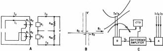
3-D multiplier with input currents representing three parameters
and output voltage giving their product (A). Dynamic characteristic curves of bridge
(B). Practical circuits relationship (C) of output voltages A and B and amplifier
current I6, can be used to carry out a large number of mathematical operations.
The increase in semiconductor resistance influenced by a weak magnetic field
may be considered as following the square law, in relation to flux density. In terms
of flux density B, the resistance R may be expressed as:
R = R0 + mB2
where R0 is the initial resistance at zero magnetic field and m in
the equation is a proportionality constant.
A magnetoresistive unit consists of a semiconductor placed in the air gap of
a magnetic core which has two excitation windings. If two semiconductors with identical
properties are used, and are arranged in a bridge circuit (similar to a push-pull
amplifier) the external resistance (Rex) is much larger than that of
the semiconductors. With one unit subjected to the influence of the sum of two variable
magnetic fields, (B1 + B2), and the other subjected to their
difference (B1 - B2), the resistance of the specimens R1
and R2 becomes:
R1 = R0 + m (B1 + B2)2
and
R2 = R0 + m (B1 + B2)2
respectively. Under conditions that the magnetic cores are well below saturation
and the core reluctance is negligibly small in comparison with that in the air gap,
inductions B1 and B2 may be considered as proportional to
the excitation currents I1 and I2.
Computing with a Magnetoresistive Multiplier
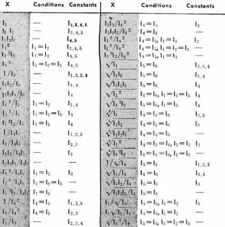
I6 = Kx = (KA/KB) (I1I2I3
/I4I5)
This relationship can be used to carry out a large number of
mathematical operations (see table).
By passing a current of equal magnitude (I3) through each unit, the
voltage difference, V, between the terminals of R1 and R2
will be
V = I3 (R1 - R2) = 4m
B1 B2 I3
or
V = K I1 I2 I3
where K is a constant which includes the factor 4m and also takes care of the
proportionality between the inducted and the exciting currents. The result is a
three-dimensional electronic multiplier whose input currents represent three parameters
and whose output voltage gives their product.
The 3-D multiplier may be reduced to a two-dimensional multiplier by keeping
one of the parameters B1, B2 or I3 constant. This
parameter will then be used to adjust the sensitivity of the device or to improve
the linearity of the composite characteristics. Some examples of practical circuits
follow.
Analog Computing Element
Since the output voltage of the multiplier is proportional to the product of
three currents, the output voltages of two multipliers, A and B, can be written
as
VA = KA I1 I2
I3, VB = KB I4 I5 I6
respectively. If the outputs of multipliers A and B are connected to a difference
amplifier, and VA and VB will be compared and, as a result,
the amplifier will supply to unit B an output current corresponding to I. This current
will become stable when VA is equal to VB; it gives the equations:
I6 = (KA/KB) (I1I2I3
/I4I5).
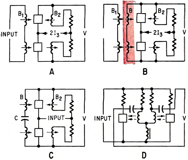
Polyphase Wattmeter
In electrical power system, the multiplier is modified by a permanent magnet
inserted in the core of the magnetoresistive unit. This allows one of the variable
magnetic fields to be kept constant. The voltage difference, V, will be reduced
to
V = (4mB1) B2I3 = K I2I3
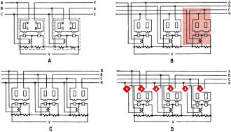
Polyphase wattmeters, (A) and (C), are modified, (B) and (D),
to measure reactive power or apparent power.
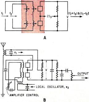
Magnetoresistive elements replace nonlinear elements in mixer
circuits (A) and modulator circuits (B) because they can operate in the multiplication
model.
Amplifier in (A) is modified with feedback winding in (B) for
a d-c amplifier. If the feedback is equal to or larger than unity and a capacitor
is connected between the feedback windings, the oscillator shown in (C) is produced.
Two capacitors in tank circuit give oscillator (D).
If the excitation current I2 of the variable field is made proportional
to the instantaneous phase current, i, of an electrical power network, while the
current I3 through the semiconductor is proportional to the instantaneous
phase voltage, so that
I2 = ki i = ki Im
sim (ωt + θ)
and
I3 = ke = ke Em
sim ωt
the output voltage of the multiplier will become V = KI2I3
V = K I1I2
= - 1/2 Kki ke Im Em
cos (2 ωt + θ) + 1/2 Kki ke Im Em
cos θ
which consists of an alternating-current and a direct-current component, the
latter being in proportion to the power of the network. It is possible to construct
a polyphase wattmeter with a single indication to show the total power consumed
in a multiphase system. Take a three-phase network as example; the circuit arrangements
are shown with those parts enclosed by the dotted lines as units of a single-phase
wattmeter. Since the current in the semiconductor is drawn from the source through
a voltage transformer, the output terminals of the units can be joined in series
so that the output voltage will be added together and the sum can be indicated by
a d-c voltmeter. Modifying the circuit produces polyphase power meters able to measure
reactive power or apparent power.
Amplifiers and Oscillators
There are many ways to construct amplifiers and oscillators. One of them is to
make two of the parameters of the three-dimensional multiplier mutually dependent,
for example B2 = k I3 so that the voltage different may be
rewritten as
V = 4mkB1I32 = KB1I32
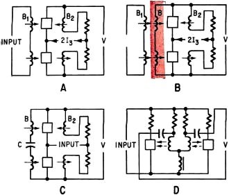
where the k's are a proportional constant. An amplifier circuit has the field
winding of B2 in series with the semiconductor and the input is applied
to the field winding of B1 which may have many turns. The amplitude of
the output voltage will be controlled by current I3 and is proportional
to its square.
An amplifier is shown with a feedback winding that may produce an induction B,
additive (or subtractive) to B1. If the mmf (magnetomotive force) required
by the magnetic path in the core is negligible, the value of B will be dependent
on the air-gap length g, the permeability in the gap μa the resistance
of the feedback winding r and the number of turns of the feedback winding N. The
voltage difference becomes
V = K I32 (β1 VNμa/2gr
or
V = K I32 β1 / (1 - KNμa
I32/2gr)
and the output voltage V is increased by the factor of
α = 1/(1 - KNμa I32/2gr)
This kind of amplifier with feedback arrangement is suitable only for d-c signals.
In the last voltage difference equation, if the feedback term
β = KNμa I32/2gr
is made equal to or larger than unity, the circuit becomes unstable and an oscillator
can be obtained by simply connecting a capacitor between the two feedback windings
and omitting the field winding of B1. Frequency f will be determined
by
f = 1/2π √(LC)
with L the total inductance of the windings and C the capacitance. Another example
for an oscillator circuit is given in (D) where two capacitors complete the tank
circuit.
Mixer, Modulator and Demodulator
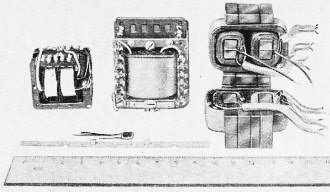
Magnetoresistive elements and three experimental multipliers
using them. Two types of magnetoresistive semiconductor elements are shown, one
imbedded between two square ferrite plates and the other deposited up on a substrate
the size of filament wire.
Since all these devices are based upon a process by which the output frequency
differs from the input signal, yet is controlled by it, the nonlinear elements,
used to achieve this purpose, can be replaced by magnetostrictive elements capable
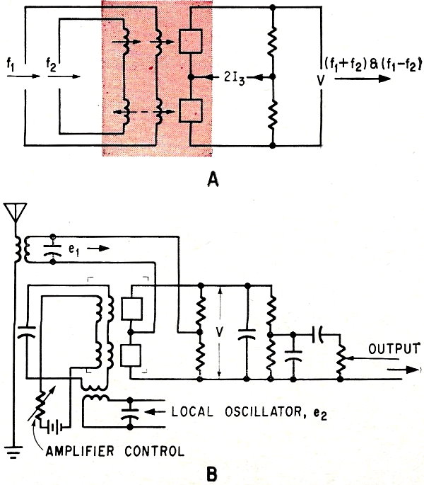
of multiplication operation. Circuit (A) illustrates a three-dimensional multiplier
as a mixer. Signals of different frequencies f1 and f2 are
fed to any two inputs of the three parameters, while the last one supplied with
d-c can be used as a means of regulating the amplitude of the output voltage consisting
of the components of (f1 + f2) and (f1 - f2).
Eventually the last parameter can also be used as the input of a third signal of
frequency f3 to mix three frequencies.
The principles of modulator and demodulator are similar and explained by an example
of a demodulator. The semiconductors bridge circuit (B) receives a modulated signal
from input terminals while one of the magnetic fields is tuned to the carrier frequency
by means of a resonant circuit and a local oscillator. The third multiplier parameter
is the amplitude control element. If the input modulated signal is
e1 = E1 (1 + M cos ωMt)
cos ωct
and the local oscillator supplies to the field winding of a signal of
e2 = E2 cos ωct
the output voltage of the three dimensional multiplier is
V = e1 e2 = E1 E2
(1 + M cos ωMt) cos2 ωct
= 1/2 E1 E2 [1 + M cos ωMt
+ cos (2 ωc + ωM) t + cos (2 ωc
- ωM) t]
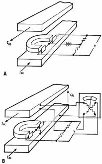
Heavy d-c measurements are possible with circuit in (A) where
heavy doc flowing through bus-bars is measured with d-c or a-c voltmeters. Arrangement
in (B) requires no extra supply for the bridge circuit and provides an accurate
measurement unaffected by doc voltage fluctuations.
The modulating term (M cos ωMt) can be filtered out by conventional
techniques.
D-C Current Transformers
This device is suggested for measurement of very heavy direct current. Using
the magnetic field of an U-shaped permanent-magnet as the constant bias field the
magnetoresistive elements are placed on the pole faces and the whole unit is situated
between the d-c bus-bars. With the bridge circuit drawing current from a d-c or
a-c supply, the heavy d-c through the bus-bars will excite a magnetic field on the
specimens and be measured with a d-c or a-c voltmeter.
If the d-c voltage of the bus-bar supplies current to the bridge, the voltage
at the output will be proportional to the power through the bus-bar. However, by
means of a quotient-measuring instrument having one pair of its terminals connected
to the output of the multiplier, and the other pair connected across the bus-bar
voltages the current in the bus-bar will be indicated by the deflection of the instrument ψ,
which is
ψ = K Vdc Idc/Vac
= K Idc
This arrangement has the advantage that no extra supply for the bridge circuit
is required. Also, the correct value of the direct current is always shown by the
instrument without being affected by doc voltage fluctuations.
Experimental Result
The perfection of a three-dimensional multiplier depends mainly on its linearity
and sensitivity. With InSB (Indium antimonide) of proper doping as the active element,
it is possible to make magnetoresistive specimens with resistance equal to 100 ohms
at zero flux density, and about seven times that amount at a flux density of 10
kilo gauss. The specimen is reproducible and almost temperature independent within
the range of ordinary working temperatures. Characteristic curves of two such magnetoresistive
specimens are shown to have identical form when the magnetic field is less than
four kilogauss. The three-dimensional multiplier constructed with these elements
will have a family of curves which are very linear when B1 and B2
are less than four kilo gauss but do not go exactly through the origin. This discrepancy
can, however, be eliminated by introducing a potentiometer of low resistance between
the magnetoresistive elements. If the external resistances Rex are connected together
through a potentiometer, and the field circuit of the individual magnetoresistive
unit is provided with tunable choke coils, the linearity and symmetry of the characteristic
curves can be adjusted. Further adjustment is possible by varying the length of
air gap in the magnetic core.
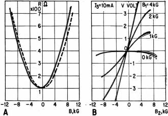
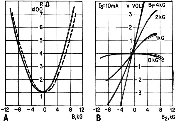
Indium antimonide used in two active elements gives identical
curves when the magnetic field under four-kilogauss (A). A 3-D multiplier using
these elements gives the family of curves in (B). The curves are linear when variable
magnetic fields are less than four-kilogauss.
Using a control current I3 = 10 ma and at B1 = B2
= 2 kilogauss, the experimental multiplier has an output voltage of 1.2 volts. Since
the magnetic fields are low, the magnetic circuit can he constructed with small
ferrite cores of very narrow air gap, and the indium antimonide which is in the
form of a thin film may be deposited directly on the pole face. The multiplier unit
can thus be made compact, shockproof and rugged.
Other advantages include lifetime of all parts in the multiplier is practically
unlimited; the multiplier is also suitable for high frequency operation up to the
megacycle range; and, the output of the multiplier can be used in regulation or
telemetering applications.
The efficiency of the magneto resistive device is always better than that of
a Hall effect device when the magnetic field is sufficiently large. To obtain higher
efficiency, the magnetic core should be composed of a material other than a ferrite,
so that larger flux densities can be applied to the specimen without approaching
core saturation.
The author thanks Professor H. Welker and H. Weiss, Siemens-Schuckertwerke, Erlangen,
Germany, for supplying the semiconducting materials used in construction of the
above units.
Posted February 20, 2019
|


")