|
April 6, 1964 Electronics
") [Table of Contents] [Table of Contents]
Wax nostalgic about and learn from the history of early electronics.
See articles from Electronics,
published 1930 - 1988. All copyrights hereby acknowledged.
|
Frequency hopping spread
spectrum, first proposed and patented by Hollywood actress
Hedy
Lamarr, relies on both transmitters and receivers to precisely tune in a
pseudorandom manner to a band of discrete frequencies in a time-synchronized
manner with each other. The faster an encoded signal hops between frequencies,
the more difficult it is for an unintended listener to decode the message. Same
goes for the number of discrete frequencies used in the spread spectrum scheme.
Modern computer programs and fast-tuning receiver systems can gather huge
amounts of information spread across a broad bandwidth and re-assemble it into
intelligible data, and if an unlimited amount of time was available to do so,
just about any message can be decoded. Historically, achieving fast tuning in
the transmitter has been much more difficult than in a receiver because of the
high powers used in the transmitter. It takes longer to create and disperse
large charge values associated with higher power circuits, especially when sharp
signals with low level sidebands and spurious noise is critical. Designing a
fast-tuning
magnetron, which is a high frequency, high-Q, narrow bandwidth vacuum tube,
was key to maintain a technological lead over adversaries.
New Magnetron Shifts Frequency Fast
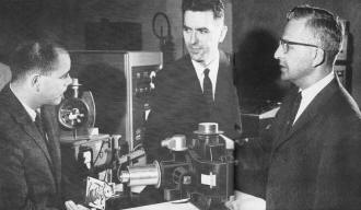
Tuned magnetron being examined by S. Ameen (right) is tuned by
motor held by J. Butler (left) while the author looks on. All are section heads
at Raytheon's Spencer Laboratory.
Random frequency agility by rotary tuning gives radar systems non repetitive
frequency patterns that deny electronic countermeasure information to enemy
By Robert E. Edwards
Spencer Laboratory, Raytheon Co., Burlington, Mass.
Radar applications often require rapid and continual shifting of frequency (called
"frequency agility") to avoid jamming by the enemy, to reduce mutual interference
with friendly sources, enhance echoes from targets or provide necessary patterns
of ECM (electronic countermeasures) or ECCM (electronic counter-countermeasures)
radiation. In a typical case, with a rotary-tuned magnetron, no pattern of repetition
occurs within 20 minutes.
The rotary-tuned magnetron, just developed, is several orders of magnitude better
than existing devices for producing this ability to shift frequency rapidly. The
tube resembles conventional magnetrons used as high-power radar oscillators but
it has a slotted disk added above the cylindrical cavities of its anode block. The
disk is attached to a shaft that is magnetically coupled to a driver motor outside
the tube. When the disk is spun, the moving slots alternately vary both the inductance
and capacitance of the anode. This produces a relatively wide frequency sweep.
Previous Methods
Until now, there were two principal means of shifting frequency: (1) the reciprocally
finger magnetron using a servo-tuned hydraulic actuator (2) cascaded broadband r-f
amplifiers.

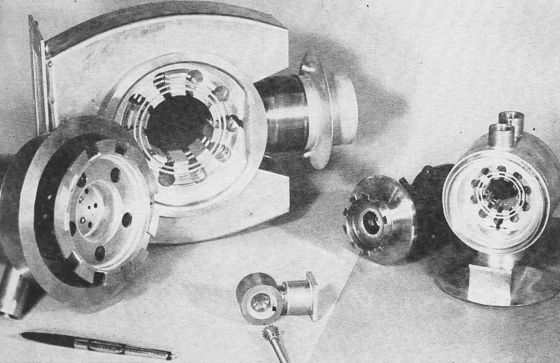
Rotary tuner (right) compared with reciprocating type (left)
shows tuning disk that does not come into physical contact with magnetron slots
as so the tuning fingers of the bellows-driven reciprocating tuner.

Solenoid lock shown at center of cross-section drawing holds
tube at fixed frequency. Capacitive transducer indicates the approximate frequency
to the receiver local oscillator.
The hydraulic servo-tuned magnetron will still be useful where a single high-power
oscillator tube is to be swept in frequency at rates no higher than 100 cps. With
the new tube, the speed of frequency shifting is 10 to 50 times as fast. The chains
of broad band r-f tube amplifiers that generate various frequencies at low power
level for amplification before delivery to the antenna are required by more sophisticated
ECM developments. But such chains often become prohibitively expensive and also
introduce a multiplicity of circuits that tend to reduce over-all reliability.
The rotary-tuned magnetron is a major step toward faster tuning with simpler,
less costly equipment. Radar systems employing this device exhibit the typical performance
advantages of frequency agility, eliminating mutual interference to friendly radar
and enhancing echoes from targets. Yet these performance advantages are achieved
with equipment that can be made small enough that it can be readily transported
even by air. Furthermore, the tube and associated circuits are simple enough to
permit existing radar systems to be modified in the field.
Interpulse Bandspread
The new tuners can be used in high-power pulsed magnetrons, so that multimegawatt
radars with a single fast-tuning r-f transmitter tube are feasible. Tuning speed
is so rapid that the tube can be tuned over eight percent of its center frequency
in the period between radar pulses.
The inherently high efficiency of the magnetron type of oscillator is retained.
Yet the complexities of the drive devices of earlier tuners or of frequency switching
equipment are avoided. Instead, the tube uses a simple, variable-speed rotary-drive
motor. Life and reliability are further increased because the forces encountered
in the continuously rotating tuner are lower than those encountered in the high-speed
reciprocating devices formerly used. There is no short-lived flexible bellows required
in the tuner assembly.
Construction
The new tube looks like a conventional tunable magnetron. It has a ceramic high-voltage
bushing, a ceramic output assembly and permanent magnets. The rotary tuner is located
at one end of the tube in the normal geometry (shown). A relatively small fractional-horsepower
motor rotates the tuner.
A small control box provides power and speed control for the motor. This control
achieves frequency agility of the r-f output. The motor is outside the tube and
torque is applied through a commercially available magnetic coupling. A major portion
of the coupling is located outside the tube and is removable, so it is unnecessary
to provide a complete magnetic coupling unit with each tube.
The basic concept of the rotary tuner is that the frequency of oscillation of
a magnetron may be changed by continuous rotation of a slotted disk suspended above
the resonant cavities of the tube. In the conventional reciprocating magnetron tuner,
the magnetron's oscillating frequency is changed by an axial motion of pins or tuning
fingers in and out of the resonant cavities as shown.
In a slow, manually tuned magnetron the tuning plunger and fingers are moved
up and down with a tuning screw and gear arrangement. However, hydraulic servos
have recently been used to increase the cycling speed. The motion is transferred
through the vacuum wall by the use of a thin flexible metal bellows that forms part
of the vacuum envelope of the tube,
The rotary tuner at the right consists of a slotted disk rotating above the anode
cavities. As the alternating slots and metallic segments of tuning disk pass over
the successive anode cavities, the composite inductance and capacitance of the anode
resonant circuit is varied, causing changes in the frequency of oscillation. The
combined LC tuning effect, in which inductive tuning occurs for one portion of the
cycle of rotation and capacitance tuning occurs over the remaining part of the cycle,
results in a wider tuning range than would be possible with either separate L or
C tuning alone.
Tuning Speed

Tuning is accomplished by rotating the toothed wheels relative
to the anode structures. Subassemblies shown are for the L,S and Ku bands.
One complete cycle back and forth across the available tuning range occurs each
time the disk is rotated past a cavity. Thus, for a ten-cavity magnetron, ten complete
cycles each way across the range are obtained for each complete rotation of the
tuner. As a result, the effective tuning speed of rotary-tuned magnetrons is high.
The tuner is suspended from bearings inside the tube, and is rotated by the magnetic
coupling shown. The tuner disk is shown as supported from the outer edge in the
sketch or from the inner edge in the photograph. The choice is dictated primarily
by considerations of end cavity resonances, tuning range and mode separation.
The three tubes shown represent L-band, S-band and Ku-band versions of the design.
From the cross sectional view it is seen that rotary tuners can often be installed
in magnetrons without need for other internal design revisions. The anode, cathode
r-f output and magnet designs may remain generally the same as in the basic prototype
tubes.
The bearings supporting the tuner are capable of speeds up to several thousand
rpm in a vacuum and must be unaffected by the 500° C bakeout temperatures used
in processing the tubes.
Several different designs of bearings were considered. Among them were specially
treated ball bearings, impregnated graphite, and glazed ceramics. The ball bearings
used in the L-band magnetron have been extensively tested at speeds up to 10,000
rpm and have operated continuously at 3,000 rpm for many thousands of hours. The
bearings are not a limiting factor in any of the rotary tuners tested.
A solenoid-activated lock or brake can be used to hold the frequency fixed. This
brake avoids any possibility of motion or wandering of the tuner angular position,
although the magnetic drive coupling is sufficiently rigid to prevent tuner angular
motion under average conditions of shock or vibration.
Feedback Indicator
There must be some indication of the approximate frequency of the magnetron so
the receiver local oscillator can be preset to the correct corresponding frequency.
One method utilizes a capacitive feedback transducer with a meshing set of capacitive
plates in which the capacitance variation as a function of angular rotation is adjusted
to resemble the frequency tuning curve of the magnetron. One set of capacitive plates
is attached to the tuning shaft while the other set remains stationary.

Transducer capacitance and tuning curves for a ten-vane L-band
magnetron show close correspondence.
These capacitive plates are divided into the same number of segments as the number
of anode cavities in the magnetron, thus producing one capacitive cycle for each
frequency tuning cycle. This capacitance variation is fed to the receiver local
oscillator as an indication of tuner position and output frequency at any instant.
The tracking of the feedback transducer with the tuning curve of the L-band magnetron
is shown. For this ten-vane tube, one half of a tuner cycle (across the frequency
range in one direction) occurs in 18° of shaft rotation, corresponding to movement
past one half of an anode cavity.
While the total frequency excursion of the L-band tube is presently rated as
100 Mc (1,250 to 1,350 Mc), bandwidths up to 200 Mc have been achieved in special
cold test models - working at very low power. Bandwidth is influenced by many factors,
such as shape of slots in the tuning disk, various characteristics of the anode
design and tuner-to-anode spacing. For instance, the 100-Mc range of the L-band
tube can be increased to 130 Mc by decreasing the spacing from 0.050 to 0.030 inch.
The main limitations thus far encountered with rotary tuners are similar to those
of the conventional reciprocating-finger type of magnetron tuners. Care must be
exercised in the tuner-to-anode spacings and in the thermal design of the tuner.
Excessively close spacings could introduce r-f arcing at high power levels.
Thermal expansion and heat distribution in the tuner components must be optimized
by selection of appropriate materials. As with the finger-type tuners, the problems
of arcing and heat dissipation factors become more critical at the higher operating
frequencies, where tube dimensions scale down so that spacings and areas are relatively
small. However, solutions to these problems have been worked out even for a Ku-band
tube.
Special shaping of the tuning curve can be accomplished by modifying the shape
of the tuner plate and the anode cavities to provide waveforms that are somewhat
trapezoidal or triangular in shape. Manipulation of the tuning curve may make these
magnetrons useful in pulse compression and frequency-scan radars.
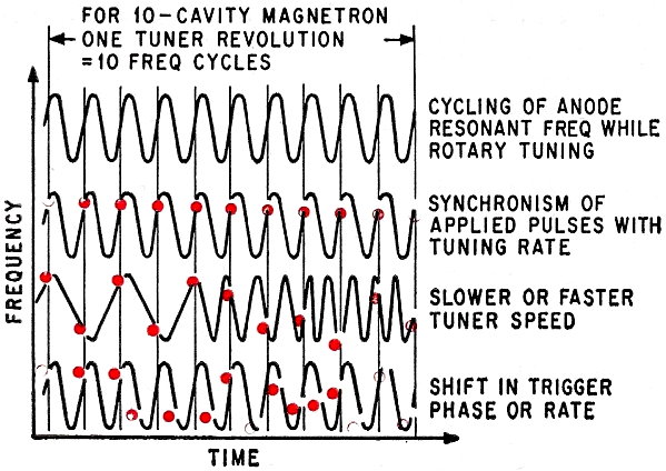
Pulse vs Speed
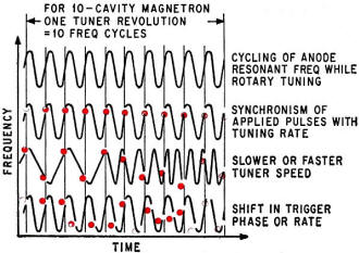
Frequency agility with rotary tuners shows the varied effects
of changing both tuner speeds and shifting trigger phase contrasted with holding
synchronism.

System of rotary tuning that might be applied as a modification
kit for an existing radar.
Frequency changes in a radar using a rotary tuned magnetron are obtained by changing
either speed or pulsing rate. As the tuner is rotated, the magnetron's resonant
frequency is continually cycled back and forth across the full available tuning
range, as shown. If the pulses applied by the radar transmitter are synchronized
with the tuner rotation rate, constant output frequency is obtained on each pulse.
Rotation speeds faster or slower than the synchronous value will result in various
output frequencies on successive pulses. The radar pulse repetition rate can remain
constant if desired. With higher rotational speeds, more than one frequency cycle
can be made to occur in the interpulse interval. By proper selection of the tuner
speed or by continuously varying it with a coded signal or a random noise source,
random output frequencies can be obtained. This condition may be required to prevent
enemy analysis of jamming. In one typical case where a rotary tuner was evaluated
in a radar system under conditions of constant pulse rate and noise-controlled variable
tuner speed, it was found that no pattern of repetition occurred over a period of
20 minutes-the duration of the detailed signature analysis.
Frequency agility can also be obtained by varying the trigger phase or pulse
repetition rate of the radar while maintaining constant tuner rotational speed,
a technique made practical by the high tuning speed. The cycling rate of the tuner
is constant, but the modulator pulses are applied at various time intervals along
the tuning curve.
This method also offers a high degree of random frequency agility, although changes
in duty cycle or shortening of the interpulse interval (affecting range) must be
handled in a manner that does not deteriorate system performance. It is often more
desirable to obtain agility by changing speed, especially when existing radars are
modified with rotary tuners. The modulator trigger circuits need not then be disturbed.
The necessary system changes involve only installation of a rotary-tuned tube in
place of the previous magnetron, addition of the drive motor and its speed controller
and revision of the local oscillator circuit. Such changes can be performed in the
field.
Interpulse Sweep
A full excursion across the frequency range of the tube-and even back again-can
easily be achieved between pulses while using moderate tuner rotation speeds. Tuning
rates up to 2,000,000 Mc per second per second can be achieved at X band on Ku band
by this technique. This speed is ten times faster than is presently attained with
X-band hydraulically tuned magnetrons. The L-band tube tunes 50 times faster than
its hydraulically tuned counterpart. The difference results largely from the use
of continuous rotation rather than reciprocating motion. Also, several tuner cycles
occur for each revolution of the tuner around the anode.
Hydraulic tuners still are sometimes preferable to rotary tuners. For example,
a hydraulic tuner is better when a stable fixed frequency is desired for several
pulses, shifting to a new stable frequency for the next group of pulses.
The elements required for a rotary tuning system modification are illustrated.
The main building blocks are the tube, its tuner drive motor, a speed control and
the tracking circuits. Initial feedback information from the capacitive transducer
of the magnetron is used for preliminary lock-on of the local oscillator and the
r-f output signal from each pulse is sampled for final lock-on, the oscillator being
held at this frequency until just before the next pulse is applied.
Standard O-type backward wave oscillators have been used for tracking the rotary-tuned
magnetrons.
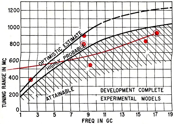
Applicational Advantages

Projected tuning ranges based upon a completed rotary tuning
development and three experimental models shows probable tuning range of better
than 1 Gc at 19 Gc. {Note: scale skew was in original print}
High speed frequency agility offers ECCM for both old and new radar systems,
thus adding a capability that can extend the useful life of many existing radars
simply and inexpensively.
Another advantage is production of enhanced target echoes, With a fixed frequency
radar or a slowly tuned system, the many components of the r-f echo from the target
can return in an unfavorable phase relationship resulting, under certain circumstances,
in weak target indication. With frequency agility, a so-called scintillation effect
occurs, in which same pulses at favorable frequencies result in strengthened echoes
and the over-all average of the echo return is increased. To ensure high detection
probabilities, it is best to see that there are both good and poor phase relationships
for each scan and that the varying frequency ensures a good average. Far a detection
probability of 85 percent, performance equivalent to an increase of 6 db in transmitter
power has been calculated and confirmed by tests with frequency agility at L-band.
High detection probability is thus achieved at longer ranges than with single-frequency
radar.
With increasing numbers of radars and other electronics equipment in the field
today, mutual interference between these systems has became commonplace. Nearby
radars often interfere with each other, requiring shifting of operating frequency.
Tests conducted with adjacent radars in which the frequency of one system could
be varied at a high speed have shown that mutual r-f interference is greatly reduced.
Seldom does an output pulse from the frequency agile radar fall at exactly the proper
frequency to be detected by the adjacent radar. When it occurs, it is only as a
single pulse rather than a succession of pulses that produce a strong false-target
indication an the display tube.
System reliability is increased by the fact that only one r-f transmitter tube
is now needed instead of a chain of high-power devices. Reliability is enhanced
in as much as only a single modulator is needed and because the tuner drive and
central circuits are simple with actuation accomplished by only a variable speed
motor and magnetic coupling. The new elements cast less, are smaller and weigh less
than comparable devices. With the continuous tuner rotation, acceleration strains
are minimized and there is no flexible vacuum seal or bellows to limit the life
of the tuner.
In addition, the common system problem of false-target indication from second-time-around
echoes (distant targets whose echoes return during the next successive receiving
interval) is completely eliminated. The receiver local oscillator frequency remains
constant far only a single interpulse interval, and any late echoes from previous
pulses at other frequencies are rejected.
Present Capability
Construction of rotary-tuned magnetrons was begun with ultrahigh frequency (400
Mc) devices. The first tube was operated at a power level of about 1 megawatt across
a 15-megacycle tuning range. Tubes have since been operated at several other frequency
bands, as indicated. The curve shows the tuning ranges known to be attainable, and
also illustrates the maximum tuning range to which these designs may be extended
by further development.
The completed L-band tubes that have undergone extensive systems testing are
presently capable of about 100 megacycles tuning range (although up to 200 Mc has
been observed in special cold test models). The S-band tubes can tune 200 Mc at
a power level of several megawatts, and the Ku-band tubes provide 60 kw aver a 500-Mc
range at present. The tests at uhf, S-band, and X-band have been primarily in the
nature of feasibility studies. In each case operable tubes have been built to demonstrate
that rotary tuners would be effective and practical in these frequency bands.
The Author
 Robert Edwards is an engineering section head
in the magnetron laboratory of the Raytheon Microwave and Power Tube Division. He
has been responsible for the development of numerous high-power pulsed magnetrons,
stabilized magnetrons, rapidly tunable tubes using hydraulic servos, initial rotary
tuner development, research for high-temperature magnetron applications and basic
studies on rfi reduction. He has also performed product engineering on infrared
detectors, and some of the early development work on Amplitron and Stabilotron devices. Robert Edwards is an engineering section head
in the magnetron laboratory of the Raytheon Microwave and Power Tube Division. He
has been responsible for the development of numerous high-power pulsed magnetrons,
stabilized magnetrons, rapidly tunable tubes using hydraulic servos, initial rotary
tuner development, research for high-temperature magnetron applications and basic
studies on rfi reduction. He has also performed product engineering on infrared
detectors, and some of the early development work on Amplitron and Stabilotron devices.
After graduation from Union College with the degree of B.S. in E.E. he was employed
at Western Electric on the development of military communications equipment. During
two years in the U. S. Naval Reserve, he studied radar, sonar and electronic countermeasures
at M.I.T. and Harvard University. He served as an electronics specialist officer
at the Naval Research Laboratory and as assistant electronics officer with the Columbia
River Group. While working at Raytheon, Edwards has done graduate work at Northeastern
University, Boston.
He is registered professional engineer in Massachusetts, a senior member of the
IEEE, and a member of the IEEE Professional Groups on Electron Devices and Military
Electronics.
Posted February 26, 2019
|


")