Optimum Coaxial Cable Diameters
|
|
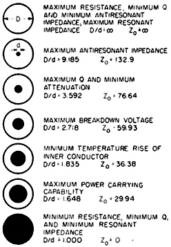
If Phillip H. Smith, an engineer notable for his varied and complex qualities, was around today, he would undoubtedly be known as "Mr. Impedance," although his humble character would resist the admittance of stardom into his biography. Anyone as adept at designing impedance matches, calculating phase changes along a transmission line, and determining capacitances and inductances, surely has, during routine tasks of his workday, calculated optimal ratios of inner and outer conductor diameters which result in minimum antiresonant impedance (∞ Ω), maximum antiresonant impedance (32.9 Ω), minimum attenuation, maximum breakdown voltage (59.93 Ω), minimum temperature rise (36.38 Ω), maximum power carrying (29.94 Ω), and, duh, minimum resistance (0 Ω). Graphics, plots, and even a nomograph are included. Optimum Coax Diameters
Fig. 1 - Quick picture of optimum coaxial conductor diameter ratios.
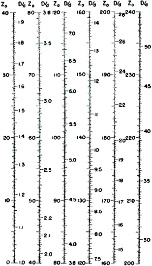
Fig. 2 - Characteristic impedance in ohms of gas-filled coaxial line for various conductor diameter ratios. By Phillip H. Smith, Technical Staff Bell Telephone Laboratories, Inc. Whippany, N. J. Equations and charts give optimum ratios of inner and outer conductor diameters for each of ten different transmission line properties. Comparison of curves speeds choice of best compromise ratio for a particular application. Expanded scales give Zo for any ratio. If the inner diameter D of the outer conductor of a coaxial transmission line is held constant and the diameter d of the inner conductor is varied, optimum conductor diameter ratios for different transmission line properties will range from one to infinity as indicated in Fig. 1. It is frequently advantageous to employ a coaxial line having a conductor diameter ratio which results in a compromise between several desirable line properties. A single compromise ratio is also desirable for certain fields of use because it simplifies manufacturing and merchandising problems. These considerations have led to standardization, in effect, of a single coaxial conductor diameter ratio for high - frequency and microwave applications1. This ratio (2.3) results in a nominal characteristic impedance of about 50 ohms. For many specific coaxial line applications, however, the design engineer may find it desirable to employ a conductor diameter ratio which will give more nearly optimum results. The derivation of the optimum ratios is briefly described and optimum values are indicated to one part in ten thousand. In all cases the medium between conductors is assumed to be a gas with a dielectric constant approaching unity, and any effect of inner conductor supports upon the optimum conductor diameter ratio for a given property is neglected. The relationship between conductor diameter ratio and characteristic impedance, as plotted on the expanded scales of Fig. 2, is based on the familiar equation Z0 = 138 log10(D/d) (1) Attenuation and Attenuators For a given frequency and conducting material the total high-frequency resistance R of a coaxial transmission line is proportional to the inverse sum of the diameters of the individual conductors:
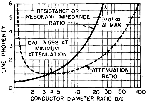
This equation shows that minimum resistance of a line of given outer conductor diameter D occurs when ratio D/d approaches unity. Minimum resistance does not, however, accompany mini- mum attenuation. As the conductor diameter ratio approaches unity the resistance approaches 0.435 times the resistance of a line having minimum attenuation, as seen from Fig. 3. Minimum attenuation, commonly referred to as loss in a coaxial transmission line, occurs when ratio D/d is 3.592. This ratio corresponds to a characteristic impedance of 76.64 ohms. As the conductor diameter ratio drops below the minimum-attenuation ratio of 3.592 the line resistance continues to decrease but the current required to transmit the same power through the line rises. For ratios below 3.592 the PR losses mount at a rate that is faster than the rate at which the resistance decreases. The attenuation constant of the line and not the resistance alone determines the overall attenuation. The attenuation constant a of a high-frequency transmission line is α = R/2 Z0 (3) Substituting Z0 from Eq. 1, α = R / [276 log10 (D/d)] (4) But from Eq. 2 R is proportional to [(1/d) -I- (1/D)]. Substituting this for R in Eq. 4, we obtain α = K * [(1/d) + (1/D)/ log10 (D/d)] (5) where K is a proportionality factor. The conductor diameter ratio corresponding to minimum attenuation is obtained by minimizing a with respect to D/d. The increase in attenuation2 as a result of departing from the optimum ratio of 3.592 is obtained from Eq. 5 when the proportionality factor K equals log10[3.592/(3.592 + 1)] or 0.121. Figure 3 shows this graphically.
Fig. 3 - Solid-line curve gives effect of D/d on ratio of resistance or resonant impedance of line to that of line having minimum attenuation. Dashed -line curve gives effect of D/d on ratio of attenuation of line to that of line having mini- mum attenuation.
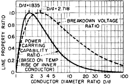
Fig. 4 - Solid-line curve gives effect of D/d on ratio of power carrying capability of line to that of line having maximum capability. Dashed -line curve gives effect of D/d on ratio of breakdown voltage to that of line having maximum resistance to breakdown
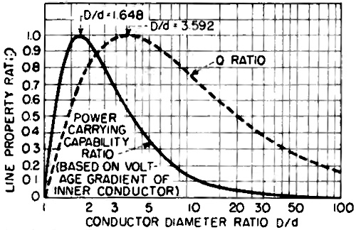
Fig. 5 - Solid-line curve gives effect of D/d on ratio of power-carrying capability of line (based on voltage gradient of inner conductor) to that of line having maximum capability. Dashed-line curve gives effect of D/d on ratio of Q of line to that of line having minimum attenuation.
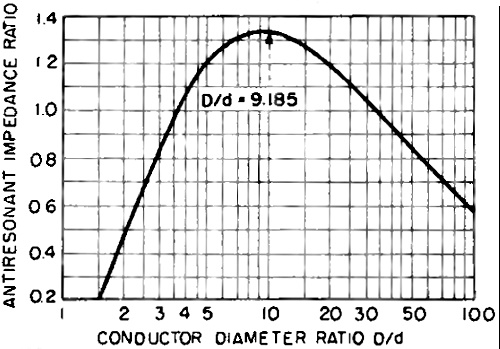
Fig. 6 - Effect of D on ratio of anti-resonant impedance of line to that of line having minimum attenuation. Heat, Voltage and Power The optimum conductor diameter ratio of a coaxial line based on temperature rise of the inner conductor may, with certain simplifying assumptions, be computed by multiplying the attenuation constant, as expressed by Eq. 5, by the area ratio of outer to inner conductor per unit length (which equals the ratio of diameters) and then minimizing with respect to D/d. An optimum ratio of 1.835 is thus obtained, which corresponds to a characteristic impedance of 36.38 ohms. The calculated3 penalty in decreased power-carrying capability based on a constant temperature rise of the inner conductor, for departing from this optimum ratio, is shown on Fig. 4. The penalty in increased temperature rise of the inner conductor for departing from the ratio 1.835 will vary for different conditions of inner and outer conductor emissivity and thermal properties of the surrounding media, and therefore can be evaluated quantitatively only in specific cases3. A coaxial transmission line will withstand maximum applied voltage between conductors when their diameter ratio is 2.718, which corresponds to a characteristic impedance of 59.93 ohms. This is determined by minimizing the formula for the voltage gradient at the surface of the inner conductor4, where breakdown first occurs, with respect to D/d. The gradient g in volts per cm at the surface of the inner conductor is g = 2 * E / (d log10(D/d)] (6) where E is the applied voltage and e is the Napierian base (2.718). The reciprocal of g gives a quantity which is proportional to the ratio of the breakdown voltage of a line to that of a line having maximum resistance to breakdown. This is plotted on Fig. 4 as a function of the conductor diameter ratio. Maximum power-carrying capability of a concentric transmission line occurs when the conductor diameter ratio equals √e or 1.648, which corresponds to a characteristic impedance of 29.94 ohms5. This assumes that the frequency is within a range (usually below about 50 mc) where voltage breakdown rather than overheating of the inner conductor governs the maximum power rating of the line. This ratio is also optimum from the power -carrying standpoint at higher frequencies under most conditions of pulsed operation where the average power is small as compared to the peak power. In order to calculate the maximum power-carrying capability ratio, based on a limiting voltage gradient on the inner conductor, we note first that the applied voltage across a transmission line terminated in its characteristic impedance is a function of the characteristic impedance and the power P in the line: E = √(PZ0) (7) But the characteristic impedance as given by Eq. 1 may also be expressed as Z0 = 60 log10 (D/d) (8) Substituting into Eq. 7, E = √(60 * P) * √[log10 (D/d)] (9) The gradient at the surface of the inner conductor for a given applied voltage is given by Eq. 6. Substituting the above equivalent for E into Eq. 6 we obtain the following expression for the gradient at the surface of the inner conductor for a given power g = 2 √(60 * P) / 2 √[log10 (D/d)] (10) The conductor diameter ratio which permits the transmission of a given power with minimum voltage gradient, and hence maximum power transmission when voltage gradient is the limiting factor, is obtained by minimizing g, as given in Eq. 10, with respect to D/d. We then obtain (D/d) = √e = 1.648. The square root of the reciprocal of the gradient as expressed in Eq. 10 gives a quantity which is proportional to the ratio of the power -carrying capability of the line to that of a line having a maximum capability, based on minimum voltage gradient on the surface of the inner conductor. This is plotted as a function of the conductor diameter ratio in Fig. 5. Antiresonant Impedance The maximum antiresonant impedance of coaxial transmission line sections is obtained when the conductor diameter ratio is 9.185, which corresponds to a characteristic impedance of 132.90 ohms6. The antiresonant impedance of a transmission line section is, in general ZAR = Z0/α (11) where α is the attenuation constant of the line. Substituting the value for Z0 given by Eq. 1, ZAR = log10 (D/d) / α (12) a Combining this with Eq. 5 then gives ZAR = log210 (D/d) / [(D/d) + 1] (13) The conductor diameter ratio which provides a maximum anti-resonant impedance for a line section is obtained by maximizing ZAR with respect to D/d. The absolute value of the anti-resonant impedance for a transmission line of optimum conductor diameter ratio (9.185) may be computed from ZAR = 3,428.82/R (14) where R is the total resistance of the line section. Resonant Impedance Minimum resonant impedance of a coaxial line section is obtained when the conductor diameter ratio approaches the limiting value of unity. As the ratio approaches this limiting value the characteristic impedance approaches zero. The resonant impedance of a line section is, in general, ZR = α Z0 (15) Substituting the value for Z. given by Eq. 1 ZR ≈ α log10 (D/d) (16) From Eq. 5, α is proportional to [(1/d) + (1/D)] / [log10 (D/d)] and the resonant impedance is therefore ZR ≈ (D/d) + 1 (17) From inspection of Eq. 17, ZR approaches a minimum value as D/d approaches unity. The absolute value of the resonant impedance for a given set of conditions may be computed from ZR = R/2 (18) where R is the total resistance of the line section. From inspection of Eq. 2 it may be seen that R (and therefore ZR) is minimum when d = D or D/d = 1. The minimum antiresonant and the maximum resonant impedance of a coaxial transmission line section is obtained when the conductor diameter ratio becomes infinitely large, which corresponds to an infinitely large characteristic impedance. As may be seen from Eq. 13 and 17, this occurs when D/d becomes infinitely large. This is shown, with respect to a line having minimum attenuation, on Fig. 3 and Fig. 6. Q Ratio If in a tuned circuit the frequency is changed from the resonant frequency by an amount Δf so that the power in the circuit is reduced to half the value at resonance (or anti-resonance), then Q = f / 2Δf (19) Defining Q of resonant (or antiresonant) transmission line sections in the same way6, Q = Z0/R * 2πl / λ where 2πl / λ is the angular length of the line section in radians and R is given by Eq. 2. The Q is maximum when R/Z0 is minimum, but R/Z0 is proportional to the attenuation of the line as shown in Fig. 3 and therefore the Q is maximum when D/d = 3.592. The Q of a coaxial transmission line section is minimum when the attenuation of the line is maximum. As may be seen from Fig. 3, this occurs when D/d approaches the limiting value, unity, and also when D/d becomes infinitely large. References (1) RMA Subcommittee on Antennas and R -F Lines-TR-31-2901 ; RMA Sub- committee on Gas -Filled Transmission Lines-TR-911. (2) E. J. Sterba and C. B. Feldman, Transmission Lines for Short Wave Radio Systems, Proc. IRE, July 1932. (3) C. R. Cox, Design Data for Beaded Coaxial Lines, ELECTRONICS, p 130, May 1946. (4) F. W. Peek, Jr., "Dielectric Phenomena in High -Voltage Engineering," McGraw-Hill Book Co., New York, Second Edition, p 28. (5) P. H. Smith, U. S. Patent No. 2,298,428, issued Oct. 13, 1942. (6) B. J. Witt, Concentric Tube Lines, Marconi Review, p 20, Jan. -Feb. 1936.
Fig. 5 - Solid-line curve gives effect of D/d on ratio of power-carrying capability of line (based on voltage gradient of inner conductor) to that of line having maximum capability. Dashed-line curve gives effect of D/d on ratio of Q of line to that of line having minimum attenuation Fig. 6 - Effect of D on ratio of anti-resonant impedance of line to that of line having minimum attenuation
Posted August 9, 2023 |
|
")