|
May 4, 1964 Electronics
") [Table of Contents] [Table of Contents]
Wax nostalgic about and learn from the history of early electronics.
See articles from Electronics,
published 1930 - 1988. All copyrights hereby acknowledged.
|
The many idiosyncrasies of atmospheric
phenomena that affect long distance communications are certainly more well known
and understood today than they were in the early days of radio. Ionization, temperature
and pressure gradients, suspended particulate contamination, and other factors have
been extensively studied, measured, and modeled. Daily and seasonal patterns are
somewhat predictable and exploitable for purposes of general use, but short term
variability that affects long distance radar measures of distance, altitude, and
speed requires near instantaneous, pulse by pulse analysis of atmospheric conditions.
Research and development of methods for accommodating short term variations that
skew measurements are an ongoing science. An extreme example of atmospheric variation
compensation is the method used by ground-based telescopes that shine lasers into
the ionosphere to create "artificial stars" whose
scintillation properties can be used in both software and adaptive optics to cancel
out apparent changes in position and intensity.
Refractivity of atmosphere may be approximated easily by measuring
dielectric constant of the air with microwave refractometer.
The Authors
Clarence H. Stewart received his bachelor's degree in engineering
from the University of Kentucky in 1949, his master's from Northwestern University
in 1960, and is currently pursuing studies at the University of Colorado leading
to a PhD degree. From 1943 until 1951 he was employed by several radio stations.
In 1951, he joined Jansky & Bailey as a project engineer. Primary duties included
high frequency antenna design and propagation analysis. In 1955 he joined Bell &
Gossett Co., becoming the chief engineer of the Electronics division. In 1960 he
was transferred to Colorado Research Division of ITT-Bell & Gossett, Inc. (then
Colorado Research Corp.) as manager of engineering and later became technical director.
He holds patents for communications and switching systems and has published several
articles on communications systems.
Gary J. Vincent received his bachelor of science in engineering
degree from the University of Denver in 1959, and has done graduate work at the
University of Utah (1960) and the University of Colorado (1963-64). From 1957 to
1959, he was employed by Denver Research Institute of the University of Denver as
a staff research assistant. Primary activity was in the field of digital computer
circuits. From 1959 to 1961 he was employed by Sperry Utah division of Sperry Rand,
in Salt Lake City, Utah, as a project engineer on ground support equipment for the
Sergeant missile system. Specific areas included digital computer logic and circuit
design, digital-to-analog conversion equipment, servomechanisms, and automatic test
equipment. In 1961, he joined Colorado Research division, ITT-Bell & Gossett,
Inc. (then Colorado Research Corp.), as project engineer.
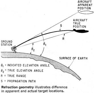
Refraction geometry illustrates difference in apparent and actual
target locations.
By Clarence H. Stewart and Gary J. Vincent
Colorado Research Division, ITT - Bell & Gossett, Inc., Broomfield, Colo.
Radar equipment is limited in accuracy by the varying medium through which it
is propagated. The Colorado Research microwave refractometer is a device capable
of making very precise measurements of the propagation medium, and is so stable
that readings are absolute rather than relative. By measuring the refractivity of
the atmosphere, it is possible to increase the accuracy of a tracking radar.
The permittivity of the atmosphere - the major factor in tracking errors - may
be easily approximated by measuring the dielectric constant or refractivity of the
air. Instrumentation capable of measuring refractivity on a real-time basis is essential.
For many years, the only practical method involved conventional meteorological instrumentation,
combined with the use of an empirically derived formula that relates the atmospheric
refractivity to the meteorological parameters; temperature, pressure, and humidity.
This "indirect" method is highly subject to error, because of sensor errors and
time constants, and also because of the uncertainty in the formula.
D. R. Hay of the University of Western Ontario designed a refractometer for balloon-supported
soundings. Hay's instrument has two capacitors which alternately control the frequency
of an oscillator. One capacitor is sealed, and acts as a reference element. The
second is open and samples the atmosphere. By comparing the oscillator frequencies
with the reference capacitor and the sampling capacitor, the dielectric constant
(and thus the refractive index) of the sampled medium is determined directly. Using
a single oscillator reduces such problems as oscillator drift and temperature variations
to second-order effects. However, measurements made with the capacitive technique
were not absolute, because the device did not have long-term stability.
Microwave Refractometer
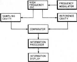
Basic technique employed in microwave refractometer is the comparison
of signals passed through a sampling cavity vented to the propagation medium and
a hermetically sealed reference cavity.
The Colorado Research microwave refractometer is stable enough to perform absolute,
rather than relative measurements of the dielectric constant. (This instrument is
the result of a joint development effort by the National Bureau of Standards Boulder
Laboratory and Colorado Research Division, ITT-Bell & Gossett, Inc.) The basic
technique involves two precision microwave transmission cavities and associated
circuitry. One of the cavities is ventilated, and acts as the sampling transducer.
The second cavity is hermetically sealed and acts as the reference element. The
output of a swept-frequency klystron oscillator is applied to the two transmission
cavities (see block diagram at top of p. 74). The outputs of the cavities will have
a relative timing which depends upon the resonant frequencies of the two cavities.
The introduction of atmosphere will affect the resonant frequency of the sampling
cavity as in the open-capacitor tuned circuit. The comparator in the unit detects
the relative timing of the detected outputs and converts this information into a
suitable form for display or recording. Several methods have been implemented for
performing the conversion. One of the earliest techniques involved the generation
of a square wave whose duty cycle was a function of the relative timing of the two
outputs. Integration of this waveform resulted in a voltage whose magnitude was
proportional to refractivity. This method provided an output suitable for operating
chart recorders and similar instruments, but was not optimum because of inaccuracies
introduced by amplifier drift, variation of klystron tuning rate with age, and related
problems associated with analog circuits. The final unit (see diagram below, left)
employed an X-band klystron frequency modulated by a 400-cps sine wave from a resonant-reed
oscillator. The two cavity outputs are combined in the comparator, which produces
two signals: one consists of the difference of the two cavity outputs; and the second,
the sum. If both cavities resonate at the same frequency, the "difference" output
is zero, and the sum output is an 800-cps signal.
Operating Principles
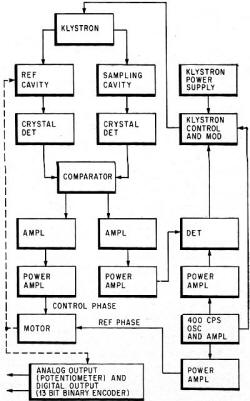
Complete refractometer illustrates use of servo motor to match
cavity resonant frequencies, and afc loop to keep klystron centered on proper frequency.
If the dielectric constant of the contents of the sampling cavity changes, the
difference output will be a signal containing a 400-cps component, the phase of
which is determined by the direction in which the cavity resonant frequency was
changed. This is applied, via a narrow-band amplifier, to the control phase of the
servo motor. The motor drives a small tuning probe in the reference cavity, causing
the resonant frequency of the reference cavity to exactly match that of the sampling
cavity. If the center frequency of the klystron is not midway between the resonant
frequencies of the two cavities, the sum output of the comparator will also contain
a 400-cps component. This output, fed back through an AFC loop, maintains the center
frequency at the correct point.
The motion of the tuning probe is converted into refractivity data by a shaft
angle encoder - for digital output - or a precision potentiometer - for an analog
output. The range of the digital readout is 0-400 N units, with a resolution
of 0.1 N unit. This range is sufficient to cover virtually any condition from
a hard vacuum to moist, sea-level atmospheres.
Calibration
Calibration of the system is accomplished with a reference cavity assembly fitted
with a multi-turn dial. This cavity has been calibrated by the National Bureau of
Standards. It indicates resonant frequency as a function of dial setting. After
the system is installed, the sampling cavity is evacuated and the mechanical portions
of the servo system are adjusted for a read of 0.0 N. The accurate operation
of the refractometer is dependent primarily on the mechanical stability of the microwave
cavities. These are carefully fabricated, using special alloys, and then plated
to obtain the desired electrical properties. Additionally, each cavity is temperature
compensated to provide an extremely low temperature coefficient (approximately 3
x 10-8°C). The resulting instrument is relatively insensitive to
variations in environmental conditions.
Need for Computation Procedure
In addition to the instrumentation requirements, it is necessary to determine
computations necessary to correct the raw data. The necessary calculations include
curve-fitting, application of Snell's Law, and numerical integration, which are
all readily performed by conventional scientific computers - for which programs
have already been written.
Definition of measuring techniques to be used is a more difficult task; in part,
because requirements for high-accuracy correction have not existed for long. Therefore,
definitive measurement procedures have not yet been developed, and there is considerable
disagreement among the various researchers regarding the optimum techniques. Proponents
of predictive techniques maintain that one-point (usually ground level) correlation
of "average" refractivity functions will provide adequate precision in the majority
of cases. At the opposite extreme would be the procedure of actually measuring the
refractivity gradient along the entire propagation path with an aircraft carrying
refractivity instrumentation.
Optimum Technique
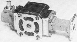
Sampling cavity is vented to atmosphere; resonant frequency varies
in proportion to the atmosphere's dielectric constant.
Generally, the optimum technique would lie somewhere between these extremes.
A typical experiment would employ a refractometer at the ground station, plus one
or two at intermediate points along the propagation path. Additional measurements
could be provided by a second refractometer in the target and others obtained either
by refractometers in aircraft or balloons. Multi-point correlation of the refractivity
function can afford a much higher confidence level in the precision of the final
results. The number of intermediate samples which should be taken is determined
primarily by the prevailing meteorological conditions. During clear weather, particularly
in dry, inland climates, relatively few measurements are required because of the
spatial and temporal stability of such atmospheres. Coastal regions, or regions
in which frontal activity is present, require an increased number of measurements
since there is a high probability of significant refractivity gradients over short
distances within much moist, unstable atmospheres.
Extreme Conditions
One example of such a situation is a very high gradient condition known as a
"duct." In a duct, the vertical gradient is sufficient to cause the propagation
path to follow a course parallel to the surface of the earth. In tropical climates
this condition may exist approximately 10% of the time, and may occur at any location
at least occasionally. Ducts cannot yet be predicted with any degree of confidence,
and may appear and disappear with little or no apparent warning. Another abnormal
condition which may exist is a refractivity inversion, usually associated with a
humidity inversion. Such a condition will cause the propagation path to bend upward.
Depending upon the extent of the inversion, this condition could result in an elevation
error greatly different from that predicted by any of the statistical techniques.
Posted June 13, 2024
(updated from original post
on 6/6/2019)
|


")
