|
February 14, 1964 Electronics
") [Table of Contents] [Table of Contents]
Wax nostalgic about and learn from the history of early electronics.
See articles from Electronics,
published 1930 - 1988. All copyrights hereby acknowledged.
|
Electronically steered phased
arrays have largely replaced mechanically steered antennas in the last couple decades.
In an effort to eliminate the need for a waveguide rotary joint, which is both expensive
and complex when built for high reliability under harsh operating conditions, Japanese
engineers developed an alternative where a small subreflector is orbited about a central
axis to produce a small scanning angle. Their efforts are presented in this 1964
issue of Electronics magazine. The measured half power bandwidth of the central
beam was about 7.5°, while the half power scan width about the main axis boresight
appears per one of the plots to be around 30° or so (if I interpret it correctly).
I assume this scheme was never pursued much beyond the experimental phase
since it does not seem to be a current standard.
Rotating Subreflector Produces Circular Scanning
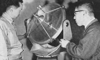
Paraboloid antenna used in the tests described in the text. This model,
being examined by Dr. Tanaka (right) and an associate, operated in X-band
Goodbye to Rotary Joints?
Conventional scanning antennas require either a rotary joint that can be both an electrical
and a mechanical weak spot or some means of varying feed line length to achieve scanning.
In this article, the authors describe a simple antenna that achieves a circularly
polarized conical scan at a high scanning rate. Moreover, this system appears to lack
the Achilles heel of its conventional counterparts since the radiator remains in a fixed
position.
Circularly polarized scanning beam is produced by a small subreflector mounted at
the focal point of a larger parabola. Circular radiation is obtained from a helical source
at the apex of the main dish
By S. Tanaka and S. Okamura, Central Research Laboratory, Shibaura Electric Co., Ltd.,
Tokyo, Japan
Many types of conical scanning antennas have been developed for homing and tracking.
However, these often have various unfavorable characteristics such as a requirement for
a rotary joint in the feed system or extended feeders.
This research was aimed at designing a conical scanning antenna from which the usual
weak points are excluded. This unit is a circularly polarized, conical scanning antenna
with rapid scan rate, no rotary joint in its feed system, and as short of a feedline
as possible. In addition, the bulk of the structure has been reduced considerably.
The array developed consists of a helical antenna, a paraboloid subreflector, and
a paraboloid main reflector. Analysis of the operation of this system has been performed
with semi-optical approximation.
Operation
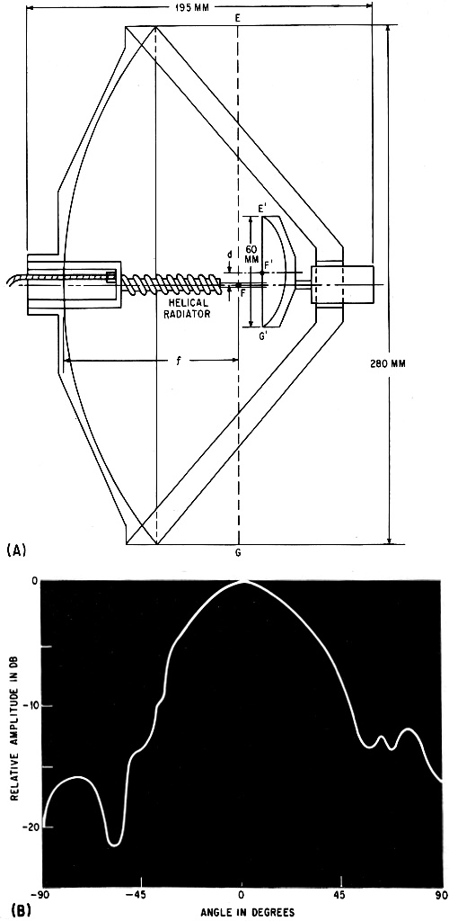
The antenna described is shown in Fig. 1. The paraboloid
sub-dish is placed face to face with the main paraboloid dish at the latter's aperture.
Theoretically, the focal plane E'F'G' of the sub-dish is centered in the focal plane
of the main paraboloid. The focal points of both the main and sub-dish are shown as F
and F. The helical antenna is designed to operate in the axial mode, and is mounted at
the vertex of the main dish with its axis placed along the principal axis. The end of
the helix is located relatively close to the sub-dish. Power is fed to the base of the
helix through a short coaxial line.
Recently developed microwave antennas with double reflectors are almost all of the
Cassegrain type.1, 2 Although this antenna also has two reflectors, it is
not Cassegrainian, but may be considered a modified Gregorian.
Fig. 1 - Diagram illustrates method used to accomplish circular scanning. The diameter
of the passive subreflector is 60 mm as compared to 280 mm for the main parabola (A),
and directivity curve for the helical radiator (B).
The helical antenna excited in the axial mode produces a circularly polarized wave
along its axis, and the wave front can be assumed to be plane in its near field. As the
sub-dish is placed close to the end of the helix, it is illuminated with a plane wave
front by the helical antenna. Therefore, the wave radiated from the helical antenna is
converged into the focal point F' of the sub-dish, while the focal point F' acts as the
primary source for the main dish. More simply, the main dish is excited by the primary
source, which is generated at the focal point of the sub-dish.
An endfire antenna such as a helical excited in the axial mode has an equivalent aperture
in its near field. The area of this equivalent aperture may be easily estimated from
the far-field pattern of the antenna.
The optimum diameter of the sub-dish should be equal to that of the equivalent aperture
of the helical antenna to reduce to minimum masking and spill-over effects at the edges
of the sub-dish.
If the focal points of both dishes coincide, a pencil beam is radiated along the principal
axis of the main dish. If the sub-dish is defocused, or rather if the focal point F'
of the sub-dish is displaced by d from focal point F of the main dish perpendicularly
to the principal axis of the main dish (whose focal length is ƒ), the radiated beam
will be tilted by Φ radians.
The relation between the defocusing angle θ = tan-1d/ƒ
and the beam tilt angle Φ, and the deterioration of the
directivity pattern as the result of defocusing, have been also investigated with semi-optical
approximation.
When the sub-dish is defocused, the phase distribution in the aperture does not remain
uniform, but becomes a cubic distribution. According to calculations, the phase differences
between the edges and the central point of the main dish are less than
π/4 radian in the test antenna.
By defocusing the sub-dish and rotating it around the principal axis of the main parabola
with a small motor, the focal point of the sub-dish (the primary source of the main dish),
moves circularly around the focal point of the main dish. Consequently, conical scanning
with a rapid scan rate is accomplished.
Performance
To check the design principles, some experiments were
performed. The main experiment involved investigating the radiation pattern of the antenna
system in X-band.
A paraboloid reflector was used as the main dish. Its aperture diameter was 280 mm
and the focal length was 105 mm. The angle subtended by the dish at its focal point
was about 135 degrees. This angle was thought to be appropriate for the operation of
this system.
A 9-turn helical antenna supported with a polystyrene rod 54 mm in length and 7 mm
in diameter was used as the feed. It fulfilled the conditions for the axial mode3.
The far-field pattern of the helical radiator is shown in Fig. 2A. The half-power beam
width was about 45 degrees.
The diameter D of the equivalent aperture of the helical antenna is estimated from
the half-power beamwidth ψ, using the equation ψ = κ λ/D.
By letting κ = 80 degrees (value selected at will), and with
ψ = 45 degrees (measured value), and A = 32 mm, then D
= 60 mm. Therefore, the diameter of the sub-dish should be 60 mm.
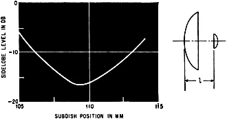
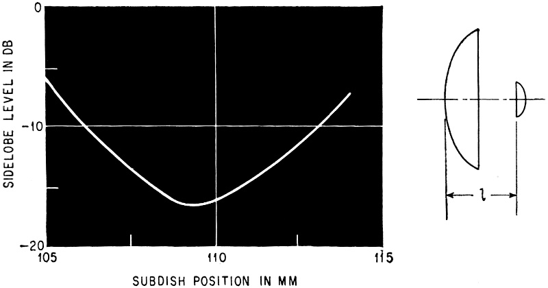
Fig. 2 - Side-Lobe level as a function of subreflector position.
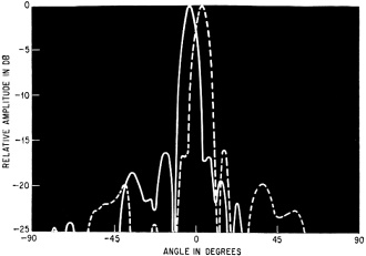
Fig. 3 - Radiation pattern of the scanning antenna-angle in degrees
versus the relative amplitude in db.
A rod antenna excited in circular polarization may be used, rather than the helical,
if desired.
A number of subreflectors varying in diameter from 40 mm to 80 mm were used in the
test. After many experiments, the optimum size of the sub-dish was determined to be 60
mm. This diameter is equal to that derived from calculations.
Side Lobes
The side-lobe level of the double-reflector antenna
system is sensitive to any change in the position of the sub-dish. The relation of the
side-lobe level to sub-dish position is shown in Fig. 2B. The abscissa shows the distance
between the apex of the main dish and the focal plane of the subreflector. The focal
plane of the main dish lies at a point 105 mm from the vertex. Figure 2B shows that the
position of the sub-dish that minimizes side-lobe level is a little farther from the
focal point of the main reflector in a direction opposite to the vertex.
Theoretically, the wave front of the radiation from the helix is assumed to be purely
plane in its near field. In practice, however, it is rather spherical, and the wave radiated
from the helix converges on a point outside the focal plane of the sub-dish. Consequently,
the optimum position of the sub-dish is slightly farther from the focal plane of the
main dish.
The radiation pattern of the conical scanning antenna is shown in Fig. 3. The full
line shows the pattern in the first quadrant of the conical scan and the dotted line
that of the third quadrant. The half power beam width is 7.5 degrees, the beam tilt angle
Φ is about 3.5 degrees, and the side lobe level is less
than -16 db.
The authors thank S. Mita for his encouragement.
References
(1) p, Foldes and S, G. Komlos, "Theorectical and Experimental Study of Wide-Band
Paraboloid Antenna with Central-Reflector Feed", RCA. Rev, vol 21, No.1, pp, 94-116,
Mar 1960.
(2) P. VV, Hannan, "Microwave Antennas Derived From Cassegrain Telescope", IRE Trans,
vol AP-9, pp, 140-153, Mar 1961.
(3) L. D, Kraus, "Antennas", McGraw-Hill Pub Co., 1950.
Posted November 22, 2023
(updated from original post on 9/21/2018)
|


")