|
January 1960 Electronics World
 Table of Contents
Wax nostalgic about and learn from the history of early electronics. See articles
from
Electronics World, published May 1959
- December 1971. All copyrights hereby acknowledged.
|
Today's electronics and
RF magazines tend to cater to engineers and managers, as opposed to technicians
and hobbyists. That's not to say that techs do not benefit from the material
presented, but that information is typically concerned with new product and
system design with little attention paid to troubleshooting and maintenance. The
predecessors to modern magazines much more often included articles on the
latter. Publications like Popular Electronics, being intended for
hobbyists, featured useful quizzes, "how to" articles, and troubleshooting tips
along with product reports and an occasional design methodology piece.
Electronics World, the predecessor to Popular Electronics, was
more of an equal split between professional and hobby themes. This particular
article tests the reader's knowledge of capacitors by proposing circuit failure
examples which are due to a malfunctioning capacitor and challenges him/her to
determine the likely cause based on observed symptoms.
Do You Know Enough About Capacitors?
 By Sol Heller By Sol Heller
In these "simple" troubleshooting and replacement problems, would you proceed
correctly every time?
Do you feel there is nothing to replacing a defective capacitor except substituting
a similar unit?
Or do you have the capacity to recognize that there is more to a capacitor than
capacitance? Here is a quiz that may turn up some surprises for you. On the other
hand, getting all the answers right should give you a charge.
Question: A service technician hesitates to use a 0.01-μf
paper capacitor as a replacement because it has been lying around (unused) on his
shelf for ten years. Is his hesitation justified?
Answer: With the exception of electrolytic units, capacitors
deteriorate only during the time voltage is applied to them. The technician should
show no hesitation about using the capacitor. Besides, if he does so little business
that he still stocks a component he bought ten years ago, how can he afford to do
anything else?
Question: Under what conditions is it preferable to connect
an audio power output tube plate capacitor between plate and screen, rather than
plate and ground, or plate and cathode?
Answer: When a capacitor of the proper working voltage is not
available, or when concern is felt, for some reason, regarding the possibility of
a breakdown in the replacement capacitor, the plate-to-screen connection may be
used. The d.c. voltage across the capacitor is much smaller in the latter case than
it would be if the negative end of the capacitor were connected to ground, or to
the cathode of the audio power output tube.

Fig. 1 - If you're alert, you would know what to look out for
in replacing C281.

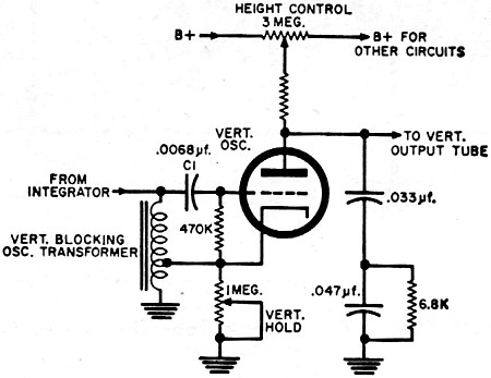
Fig. 2 - The proper replacement for one capacitor here can lick
vertical drift.

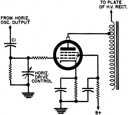
Fig. 3 - A common procedure used in replacing C1 could
cause later difficulty.
Question: Can a conventional 10-μf electrolytic capacitor be
used to replace L; in the C281 in the circuit shown in Fig. 1?
Answer: No. When the receiver is fully warmed up, the negative
side of the capacitor is at "B+" potential, while the positive side is at the higher
boosted "B+" voltage. A conventional capacitor could be used if this condition prevailed
at all times, since the negative side of the capacitor would always be at a lower
potential than the positive side. The condition does not prevail at all times, however.
During the time the receiver is warming up, the boost voltage is lower than "B+."
The negative side of C281 is consequently connected to a higher positive
potential than the positive side. The capacitor operates at this reversed polarity
for about 10 to 15 seconds. A conventional electrolytic capacitor would bite the
dust prematurely if exposed to such topsy-turvy conditions. A special semi-polarized
unit is used by some set makers and available from them.
Question: C1 in the vertical oscillator circuit shown
in Fig. 2 is a ceramic disc coupling capacitor. What type of capacitor can be substituted
for it when vertical drift is a problem, and tests have indicated that the vertical
oscillator tube is not responsible?
Answer: Substitution of a silver mica capacitor would be a logical
procedure. The mica type has a very high electrical stability. A 1000-μμf. unit,
for instance, will exhibit a capacitance change of less than .1% over a frequency
range extending from low frequencies to 2 mc. The effect of a 1°C change in temperature
is a change in capacitance of only 60 parts in a million. The tolerance of the replacement
capacitor is not important - the vertical hold control setting will produce the
correct frequency of operation even if the capacitor is 10 or 20% off its nominal
capacitance. The important thing is that the capacitance, whatever it is, doesn't
change with temperature.
Question: What harm, if any, is there in using a somewhat larger
value of capacitance than called for in replacing the coupling capacitor between
horizontal oscillator and horizontal output tube (C1, Fig. 3).
Answer: A larger value of coupling capacitance will increase
the amount of horizontal sweep signal applied to the horizontal output tube. The
horizontal drive control may have to be reset to some point close to one end of
its range, leaving an insufficient margin for readjustments necessitated by aging
or replacement of tubes or components in this circuit.
Question: Why is it undesirable to mount an electrolytic capacitor
in an area where considerable heat is likely to develop during receiver operation?
Answer: Heat is bad because it promotes drying out of the electrolyte.
This increases the series resistance offered by the capacitor; and the power factor
(ratio of resistance to impedance in the capacitor) goes up in consequence. A higher
power factor is undesirable, since larger I2R losses occur across the
increased resistance of the capacitor, and produce still further heating of the
unit. Heat also tends to increase the leakage current of the capacitor (see Fig.
4), which promotes greater I2R losses in the capacitor, and additional
heating of the unit.
Excessive heating spells death to electrolytic capacitors. In some types, every
10°C increase in temperature causes a 50% decrease in life expectancy; others are
less affected by temperature. In general, however, keeping cool is as important
for capacitors as it is for people.
Question: A technician, in replacing a power supply electrolytic
capacitor that has failed prematurely, decides to leave off the insulating cardboard
that was present around the original unit. Does this procedure make sense?
Answer: It does. The cardboard insulation prevented the capacitor
from dissipating heat adequately, and could be responsible for premature failure.
But watch for exposed voltage.
Question: What kind of electrolytic capacitor will function
more satisfactorily than other kinds under high-temperature conditions?
Answer: A capacitor that has a hermetically sealed metal can
for its container. This construction minimizes loss of electrolyte, and therefore
increases life expectancy. Any capacitor with a voltage rating 50 to 100 volts higher
than the operating voltage can be used at temperatures up to 185°F. Temperatures
in excess of 140°F may damage a conventional capacitor if its voltage rating
is not much above the operating voltage.
Question: Are there any applications in which it would make
a difference whether an electrolytic capacitor was fabricated with an etched-foil
anode or a plain-foil anode?
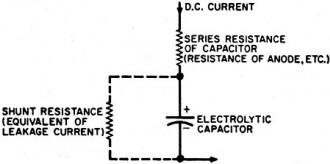
Fig. 4 - An improperly mounted electrolytic may start a vicious
trouble cycle.

Fig. 5 - Special problems go with special units, like (A) the
ceramic feed-through and (B) parallel-lead tubular.
Answer: Yes. Dry electrolytic capacitors have anodes made of
plain, etched, sprayed, or fabricated foil. An etched-foil anode is one that has
been made very rough by special processing. The resultant surface undulations give
the anode (which forms one plate of the capacitor) a much larger effective area.
The electrolyte (which forms the second plate of the capacitor) follows the undulations.
The capacitor, in consequence, has a much larger capacitance than a plain-foil unit
of the same size would have, permitting compactness.
However, an etched-foil capacitor will have a considerably higher total impedance
than a plain-foil equivalent, making the former inferior for certain applications.
A unit that does not have an etched foil would be preferable for bypassing and decoupling
in audio-frequency and vertical sweep circuits. The catalogues of parts supply houses
are often useful in determining whether a specific electrolytic capacitor does or
does not use an etched-foil anode.
Question: What effects, if any, do low temperatures have on
electrolytic capacitors?
Answer: For most conventional types, the capacitance decreases
rapidly below temperatures of -5°C. We can conceive of a situation where a battery
portable in which an electrolytic capacitor has been replaced is returned to the
service technician for further work because it didn't operate satisfactorily outdoors
in very cold weather. This temporary condition clears up when the receiver and its
owner sensibly return to a comfortable position by the fireside, or when the weather
gets a little warmer. If necessary, higher-cost tantalum capacitors may be used.
Some of these are rated for operation at -55°C, or even lower.
Question: In the case of a ceramic feed-through type of capacitor
(as shown in Fig. 5A), are there any visual indications that might point to the
need of replacement?
Answer: This type should be replaced if the silver-coated surface
is peeled, or if the ceramic is cracked, or if the center conductor of the unit
is loose.
Question: Does it make a difference in which position an electrolytic
capacitor is mounted?
Answer: It may, especially if the unit is a wet electrolytic.
An incorrect mounting position may reduce the effective capacitance. The unit should
be mounted in an upright position in such a way that the vent (for escaping gas)
is unobstructed.
Question: True or False: When an electrolytic capacitor begins
to cause circuit malfunction, it is always necessary to replace it.
Answer: False. Take the case where the only change causing the
trouble is an increase in r.f. impedance of the unit, impairing its ability to bypass
higher frequencies. Bridging it with a non-electrolytic type of smaller value but
of the proper voltage rating (for example, a 0.1μf paper unit) will generally eliminate
the trouble.
Question: True or False: If a replacement filter capacitor doesn't
function properly as soon as it is put into a radio (i.e., hum is heard), it should
be replaced immediately.
Answer: False. It should be given a chance to reform. When an
electrolytic capacitor has been idle for several months, initial leakage current
may be high enough to introduce hum because the component has deformed while not
in use. If the receiver is left in operation for 20 minutes or so, the capacitor
will generally be restored to normal functioning.
Question: True or False: When a capacitor that is mounted on
a printed board is to be replaced, it may become necessary to consider more of its
characteristics than is ordinarily the case.
Answer: True. The physical configuration may become important
in addition to the electrical properties. Take the paper tubular capacitor with
phenolic case shown in Fig. 5B. Parallel leads permit the unit to be plugged into
a printed board, after which it is soldered in place. It would be quite difficult
to fit a conventional capacitor of the same nominal value with axial leads into
the proper space, in most cases.
Posted May 9, 2019
|