|
December 1965 Electronics World
 Table of Contents
Wax nostalgic about and learn from the history of early electronics. See articles
from
Electronics World, published May 1959
- December 1971. All copyrights hereby acknowledged.
|
This "Operation of a High-Quality CCTV Camera"
article from a 1965 issue of Electronics World magazine interests me
not necessarily because I am interested in CCTV's but because it has many
similarities to the video mapper system used in the radar system I worked on in
the U.S. Air Force. It was probably built around the same era, so no surprise
there. The combination of analog and digital electronics is likely one of the
earliest examples of such an integration. The digital portion is for timing, not
video processing. An electromagnetically scanned vidicon tube is the heart of
the system. Rather than using the television type composite timing/amplitude
signals that require complex circuits to deconstruct and direct portions of the
signal to appropriate circuits, this is truly digital timing. In fact, the
timing diagram show here is one of the earliest I recall seeing in these vintage
magazines.
Operation of a High-Quality CCTV Camera
 By Gerald L. Hansen / Cohu Electronics,
Inc. By Gerald L. Hansen / Cohu Electronics,
Inc.
Electromagnetically scanned vidicon, broadcast-type interlaced sync, automatic
vidicon target control, and digital-type techniques make this approach much more
sophisticated than those usually encountered.
Since the advent of the transistor and subsequent miniaturization of associated
components, a constant revolution has been taking place in the field of closed-circuit
television (CCTV). In the past, cabinets bulged at the seams with power supplies,
cumbersome amplifiers, and sync generators, while cooling fans desperately tried
to maintain a reasonable temperature. High-quality CCTV units are available today
that can be held comfortably in one hand and outperform their predecessors in almost
every respect. A typical unit may contain deflection circuitry, video amplifiers,
broadcast-type interlaced sync generators, power supplies, and perhaps an r.f. modulator,
yet may require less power than a standard 10-watt light bulb.
Units of this type are being utilized increasingly in industry and business and
are in fact finding such widespread use that the average technician may suddenly
find himself confronted with the rather awesome task of servicing one. These systems
are also creating employment opportunities for technicians in areas considered-until
now-highly unlikely. The range of applications is broad-mining and drilling operations,
research laboratories, churches, schools, hospitals, prisons, factories, and homes.
The prediction that a television camera and TV tape recorder will some day replace
the home movie camera seems close to realization.
However, there is surprisingly little information available through normal channels
for those who would like to become familiar with these latest CCTV systems.
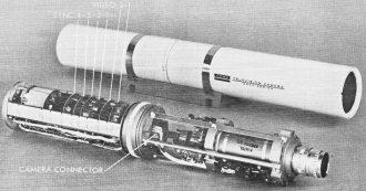
Vidicon

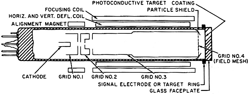
Fig. 1 - Internal arrangement of an electromagnetic vidicon.

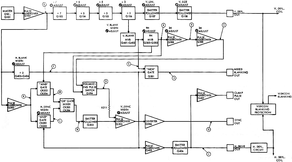
Fig. 2 - Block diagram of the broadcast-type interlaced sync
generator as used in the high-quality CCTV system described.
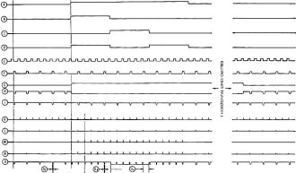
Fig. 3 - Waveforms present in the sync generator. Letter identifications
are keyed to block diagram of Fig. 2.
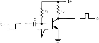
Fig. 4 - Operation of a pulse narrower.
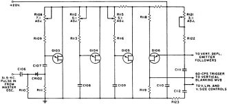
Fig. 5 - Unijunction countdown circuit divides by 525 to generate
60-cps pulse.
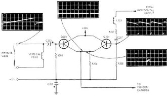
Fig. 6 - Vidicon protection circuit operates if pulses foil.

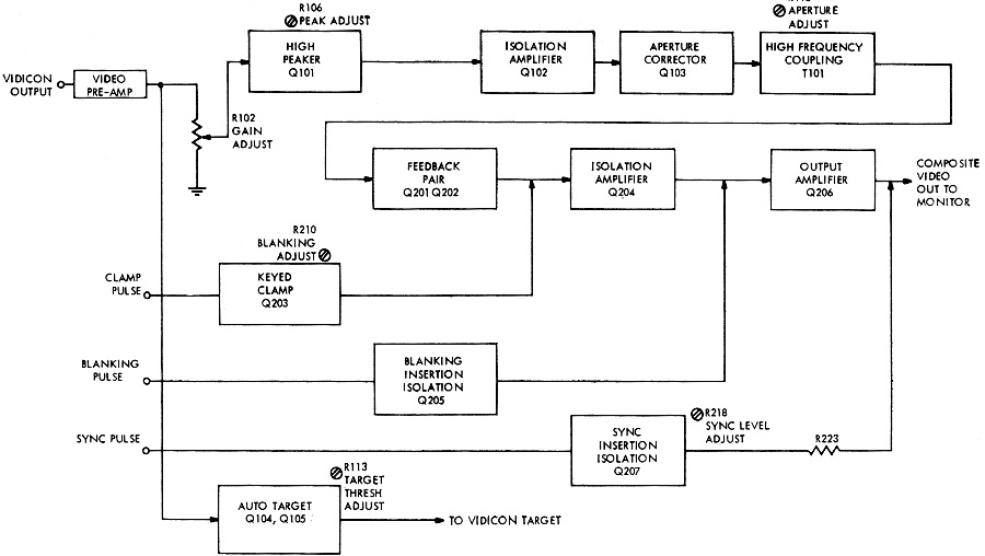
Fig. 7 - Over-all video amplifier accepts vidicon and sync generator
signals to produce the composite video output signal.

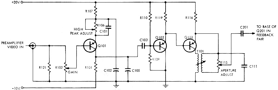
Fig. 8 - Video amplifier uses high-frequency compensation in
the first stage and high-frequency aperture correction in the last.
The vidicon (Fig. 1) might be called the "heart" of a CCTV system, It has the
important function of converting the image focused upon it into electrical signals
that can be amplified and processed for final use in the monitor or receiver. Directly
behind the glass faceplate of the vidicon is a transparent electrode coated with
a layer of photoconductive material. This layer is called the "target." The target
material varies in resistance in proportion to the amount of light falling upon
it. When the beam emitted from the cathode strikes the target material, the brilliantly
illuminated portions offer less resistance and pass the electrons more readily than
do the dark areas. A positive voltage applied to the target electrode drains these
electrons through a resistor, causing a signal to be developed. Therefore, when
the beam is scanned across the target (exactly as is done on a TV picture tube),
a video signal is developed that contains all the information necessary to reproduce
the scene focused upon the target.
The vidicon can be thought of as a miniature picture tube operating in reverse
(converting light into signals rather than signals into light). As shown in Fig.
1, grid #1 controls the amount of electron beam allowed to pass from the cathode
to the target, accelerating grid #2 speeds up the electron flow, while focusing
grid #3 controls the spot size. Beam deflection is accomplished electromagnetically
by placing a yoke around the tube. An electromagnetic focus coil is also incorporated
in the yoke. An alignment magnet completes the setup.
Circuit Operation
Fig. 2 is a functional block diagram showing one method of obtaining the necessary
deflection signals for the vidicon yoke while also providing the broadcast-type
sync which is necessary for a stable 2:1 interlace of the horizontal lines in the
raster on the monitor picture tube. Fig. 3 illustrates the waveforms found in that
circuit. The characteristic reliability and stability of this system are such that
it has been accepted for use in commercial' broadcast TV.
Operation is timed by master oscillator Q101, operating at a frequency of 31.5
kc. Its output supplies succeeding stages to provide the necessary horizontal, vertical,
blanking, and clamp signals.
Several pulse narrower circuits are utilized to shape and control the duration
of various pulses throughout the circuitry.
Fig. 4 shows the basic pulse narrower. Under no-signal conditions, R1 supplies
the bias current to saturate the n-p-n transistor, reducing the collector voltage
to approximately ground potential. Negative-going pulses are differentiated by the
RC network while the emitter-base diode action clips the positive transition. The
negative input drives the transistor out of saturation, producing a positive pulse
at the collector. Pulse width is determined by the values of R1, C, and the input
pulse amplitude. All n-p-n narrowers operate in the same manner, but the p-n-p narrower
differs only in input and output polarity. If R1 is made variable, output pulse
width may be varied.
The master oscillator output is fed through pulse narrower Q102 (Fig. 2) into
frequency-dividing network Q103, Q104, Q105, and Q106 (shown schematically in Fig.
5) that provides a total division of 525 for an output frequency of 60 cps. Unijunction
relaxation oscillators are used for the dividers and are triggered in the following
manner. The positive output from pulse narrower Q102 is applied through CR102 and
C107 to the emitter of Q103. Resistor R108 is adjusted so that the circuit's natural
period of oscillation (determined by the RC time constant in the emitter circuit)
allows Q103 to fire on every seventh input pulse. The resulting conduction through
Q103 produces a negative pulse across the "B+" series resistors. The negative pulses
thus derived are felt at base #2 of Q104 as triggering, and this stage is adjusted
to divide by a factor of five. Q105 and Q106 are each triggered in the same manner
by the stage immediately preceding each one and are adjusted to divide by five and
three respectively.
Since the waveform at the emitter of Q106 is a sawtooth, it may be utilized as
a source of vertical deflection. It is linearized by a feedback arrangement in emitter
follower Q107 (Fig. 2) and applied to emitter follower Q108 where a simple amplitude
adjustment allows control over vertical size. The linearized, shaped, and amplified
sawtooth is applied directly to the yoke for vertical deflection.
It should be noted that Q106 also provides an output at its base 1 terminal.
In Fig. 2, it can be seen that this output is fed into the vertical blanking multivibrator,
Q401-Q402. This is a one-shot or monostable multi vibrator with a variable-width
output used to obtain a positive pulse of the width needed for vertical blanking.
This pulse, in turn, is fed into a nor gate (Q301) to be inverted and mixed with
horizontal blanking. It later will be superimposed on the video waveform and used
for blanking information in the monitor.
Horizontal blanking is obtained by dividing the master oscillator frequency by
two and shaping the output into a pulse of the required width. This is accomplished
by transistors Q403-Q404 which constitute an astable multivibrator having a natural
frequency of approximately 15,750 cps. Triggering of this circuit is accomplished
by feeding it the 31.5 kc. from pulse narrower Q102. Due to the time constants inherent
in the circuit and the input pulse amplitude, the circuit uses every second pulse
as a trigger and changes state accordingly, giving a variable-width pulse output
to be combined with the vertical blanking in nor gate Q301. The multivibrator output
is also routed to pulse narrower Q405 and emitter follower Q406 to shape a horizontal
drive pulse used to develop the horizontal deflection component for the vidicon
yoke.
The trailing edge of the horizontal drive pulse from emitter follower Q406 is
used by pulse narrower Q407 to develop a clamp pulse which is routed to the video
amplifier to maintain the black reference level during vidicon retrace.
Vidicon Blanking
Circuit configuration for the vidicon protection and blanking function is shown
in simplified form in Fig. 6. The collectors of Q203 and Q204 (not sync transistors
Q203, Q204) are common to each other, and connection is made to the vidicon. Normally,
the vidicon cathode is slightly negative in potential to assure proper emission
of electrons. However, during the negative-going retrace portion of the horizontal
and vertical deflection waveforms, either Q203 or Q204 will be driven into saturation.
This causes the +20 volts applied at the emitter of the conducting transistor to
be felt at the vidicon cathode, forcing it into cut-off. Thus, the vidicon will
be blanked during retrace time.
We now have derived all of the drive and blanking pulses that are necessary for
proper operation of a CCTV system. The final requirement is a synchronizing signal
that can be added to the video output so that the monitor deflection oscillators
will operate synchronously with deflection oscillators of the camera system.
Probably the easiest way to understand the operation of the sync circuitry is
to refer to the waveform diagram shown in Fig. 3, keyed to the block diagram of
Fig. 2.
The output pulse width of narrower Q202 determines the delay of the sync pulses
(O) with respect to the blanking pulses (H). This produces the familiar front porch.
The output from narrower Q202 is fed to two and gates. For and gate 1 (CR201-CR202)
to conduct, there must be a pulse present from the horizontal blanking multi vibrator.
Therefore, the 31.5-kc. signal has every second pulse blocked, and the output from
this gate is at the rate of 15,750 cps (L). An adjustable resistor provides control
over horizontal sync width by setting the amplitude of the pulse (L) felt at the
following or gate. And gate 2. (CR203-C R204) conducts only during the 9H pulse
(A). (This pulse-width duration is nine times that of one complete cycle of the
horizontal frequency and is keyed by the vertical blanking multivibrator.) Output
of and gate 1 is mixed in the or gate with the output of and gate 2. The output
(N) of the or gate is fed through emitter follower Q203 to sync pulse narrower Q205.
Because the sync pulse narrower uses the trailing edge of its input pulses, a time
delay is achieved which determines front porch width.
The RC time constant of sync pulse narrower Q205 circuit is adjusted to provide
the pulse width (OA). However, during equalizing-pulse time (OB),
switch Q204 is turned on, connecting R211 in parallel with the sync width control.
This changes the output-pulse width of narrower Q205 to that of equalizing pulses.
The sync-equalizing interval-pulse switch Q204 is operated by pulses from the
9H multivibrator Q302-Q303 and the second 3H pulse narrower Q305. It can be seen
from the waveforms that the equalizing-pulse switch conducts during the 9H interval
but is interrupted for a period of 3H by the output of pulse narrower Q305 as shown
in Fig. 3 (D).
Video Signal
Fig. 7 is the functional diagram of a typical video chain. Output from the vidicon
is amplified initially by a video pre-amplifier consisting of an emitter-follower
input stage to match the high-impedance output of the vidicon to the lower impedance
of the following transistorized amplifier circuitry. Gain of the circuit is approximately
30 db and is accomplished by a feedback pair arrangement that tends to flatten the
over-all frequency response of the preamplifier. An emitter follower provides isolation
and impedance matching.
The output from the preamplifier is routed into the main amplifier through "Gain
Adjust" R102. Fig. 8 shows this control and the three interesting stages that follow
it. Q101 has a variable resistor and capacitor network in its emitter circuit to
provide frequency-selective amplification, thus compensating for attenuation of
higher frequency components which occurs in the preamp input stage as a necessary
adjunct to maximum signal-to-noise ratio. If this resistance (R106) is set too low,
trailing whites will be observed behind black information on the monitor. If it
is set too high, trailing blacks will be in evidence. Proper adjustment gives sharp,
clearly defined lines and edges to a televised test pattern. It effectively compensates
for amplifier input capacity. Q102 is an emitter follower for isolation and impedance
matching.
Q103, T101, and R115 form an aperture-correcting circuit. This is necessary because
the finite size of the scanning-beam spot in the vidicon smears the sharp transitions
between whites and blacks. T101 has a resonant frequency at the upper end of the
bandwidth curve, in this case 9 mc. It can be seen that with R115 set at its extreme
end toward the emitter, T101's secondary is effectively shorted out and no aperture
correction will be in evidence. However, as the arm of the pot is advanced, the
high frequencies coupled through T101 will be felt in the following amplifier stages.
Thus, the amplitude of the higher frequencies has been increased with respect to
the lower frequencies, providing greater contrast of detail in the high-frequency
portion of the televised scene.
As shown in Fig. 7, this circuit is followed by more amplification and isolation
stages to the final output amplifier Q206. Note that the drive, blanking, sync,
and clamp pulses previously described are finally put to use by simply adding them
to the video signals.
The final block remaining on Fig. 7 is labeled "Auto Target." It is the function
of this circuit to automatically adjust the vidicon target voltage to compensate
for any change in light level on the scene that is being viewed. This is done by
feeding the video from the preamplifier into a detector circuit. The detector out-put
(a d.c. voltage) is then amplified to provide a target voltage dependent upon the
preamplifier output. Increasing scene illumination results in a decrease of target
voltage. Target voltage thus derived has an advantage over the simple photocell
method sometimes used in that it is a function of the image focused on the vidicon
rather than the integrated incident light from a broad area. Various lenses may
thus be used without affecting operation.
Power Supplies
The system under discussion requires a +22 to +30 volts d.c. and draws approximately
400 ma. of current. The input voltage is reduced to a regulated +20 volts and is
utilized in various parts of the system to supply circuit requirements. It is also
used to power a converter which has outputs of -10, +450, and -225 volts. Since
a CCTV system constitutes a stable load (no significant changing of parameters to
vary the current drawn), all voltages are regulated by regulation of the +20 volts.
Posted November 29, 2022
|