New Coax Connector Tops Performance Records
|
|
APC-7 (Amphenol Precision Connector - 7 mm) coaxial connectors were standard on network analyzers by the time I entered the microwave design and manufacturing field in the late 1980s. The test equipment we used for maintaining the S-band airport surveillance radar in the USAF (early 1980s) used N coax connectors, and I cannot recall what was used for the X-band precision approach radar. SMA coax connectors were developed in the 1960s, same as the APC-7 connectors, but I don't remember seeing an SMA until I started working for General Electric Aerospace Electronics Systems Division in Utica, New York, after graduating from the University of Vermont in 1989. GE was also where I was introduced to APC-7 connectors. The 'genderless-ness' of them surprised me. Mr. Patrick Fitzgerald, my friend and mentor at GE, introduced me to the proper use and care of an APC-7 connector as they were part of the S-parameter test set on the HP8510c network analyzer. This article introducing the APC-7 coaxial connector appeared in a 1969 issue of Electronics World. New Coax Connector Tops Performance Records By Henry Pessah Advanced Product Planning Mgr., Amphenol RF Div.
Close-up of the new 7-mm, 50-ohm precision coaxial connectors. The 7-mm dimension refers to the inside diameter of the outer conductor of the matching rigid coax. The price of some high-frequency connectors may seem ridiculously high but let's look at the performance one obtains. Let's also take a look at the design and manufacturing costs and the rather involved testing techniques. "Thirty-five dollars for just one coaxial connector? Why?" Many electronics engineers, used to paying 55 cents for a standard type of coaxial connector, ask this question. However, the one we are talking about is the 7-mm, 50-ohm "precision connector." The key is performance. The connector offers constant impedance (50 ohms ±0.1 ohm) over a frequency range of 0 to 18 GHz, and s.w.r. (standing-wave ratio) for a mated pair is less than 1.003 + (0.002 X frequency in GHz). For example, 1.003 + (0.002 X 18) = 1.039 s.w.r. at 18 GHz. The connector also offers r.f, leakage better than 120 dB (this is the ratio of the leakage of a mated pair to the signal level), electrical length held to ±0.002 in, and low contact resistance: 1.0 milliohm for the inner contact; 0.1 milliohm for the outer. Insertion loss (dB) for a mated pair is less than 0.007*sqrt(freq. GHz). For example, at 16.0 GHz, loss is 0.028 dB. "Yes, but who needs performance like that?" is the next question. The answer is summed up by John Cardoza, product manager of Hewlett-Packard's Microwave Division: "Rapid advances in microwave technology, triggered to a large extent by the application of solid-state devices and techniques, have brought about the need for measurement techniques and equipment which will give the microwave engineer more information about design - and with significantly higher measurement accuracies. With the advent of solid-state devices for microwave applications (such as "bulk-effect" oscillators, microwave transistors, thin-film amplifiers and mixers, etc.), the equipment or systems designer can now achieve his end product by combining or cascading smaller, "simpler" devices and networks. If the over-all design objectives are to be achieved, the designer must be able to completely characterize the individual elements or networks so that their performance in the final system is fully predictable, and he must be able to do this characterization simply, rapidly, and accurately over wide frequency ranges. "One of the objectives of the Hewlett-Packard Network Analyzer, designed to fill this need, was to make it one of the most accurate phase and amplitude measuring instruments. For this reason it was decided to use the new precision connectors. These are some of the reasons for the choice: "1. The connectors offer the lowest s.w.r. over the widest coaxial bandwidth now available. This results in lower mismatch errors when making transmission and reflection coefficient measurements. "2. Phase measurements require a precisely determined reference plane. The connector's singular and nonambiguous mating plane makes it ideal for the precision now required in phase measurements. "3. The connectors are also employed on high directivity broad-band couplers used in the reflection tests units for reflection-coefficient measurements. Again, the low s.w.r. was one of the critical characteristics in achieving the high directivity needed for accurate impedance measurements in broad-band coaxial systems. "4. Because designers must often make measurements in other connector configurations, availability of low s.w.r. adapters is important. Adapters from precision connectors to type N, SMA, TNC, GR900, etc., provide the analyzer user this flexibility."
Fig. 1. Assembly drawing of the 7-mm coaxial connector. The mechanical tolerances are held to 0.0001-inch and manufacturing is done in clean room. The applications horizon for the precision connectors is widening. It now appears on nearly all types of precision test instruments. In equipping modern test instruments with these connectors, orders of magnitude improvement in residual error have been accomplished in the measuring system. Even for capacitance, resistance, and inductance standards operating at lower frequencies, the fixed plane and controlled residuals in precision connectors have added considerably to ultimate accuracy. In the microwave region, coaxial measurements can now be made with precision heretofore possible only in waveguide systems. Achieving the Performance To achieve high performance, mechanical tolerances required in the connector manufacturing process were carefully chosen. Both the inner and outer coaxial cross-section diameters had to be held to tolerances of 100 microinches. These tolerances were necessary to maintain proper impedance, electrical length, and to avoid excessive tolerance build-ups on assembled component parts which could result in the electrical degradation of the connector. Fits among the airline, connector body, bead assembly, and contact assembly have to be extremely close in order to avoid degeneration due to eccentricity of the center conductor. For any connector manufacturer to achieve this, a properly controlled environment is necessary. For example, the 7-mm precision connectors are manufactured in a clean, positive-pressure area where temperature is maintained at 70° ±2°F. To manufacture the connector economically, precision machining methods and instrumentation capable of holding close tolerances had to be developed: Included are Swiss Bechler automatic screw machines, Kummer automatic chuckers, and a Harding lathe with an automatic sequencing attachment. In the manufacturing process, every attempt had to be made to eliminate human variability in critical assembly operations. This was the purpose of the automatic devices. The utilization of automatic equipment not only lends itself to economic production, but assures a uniform product within the necessary close dimensional limits. The Amphenol production facility is capable of holding length and diameter dimensions within 0.0001 of an inch. And tolerances of this kind are a "must." Should they vary even slightly, the s.w.r. of the connector can jump drastically. Critical Inspection
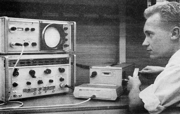
Engineer uses special microwave network analyzer to check reflection coefficient of an X-band filter. The test instrument is equipped with the new APC-7 precision connectors. Naturally, the close tolerances of the 7-mm connector necessitate unusual inspection methods. Mechanical inspection of critical dimensions on connector parts is done with air gages, precision dial indicators, and by optical methods (comparator and microscopes). In fact, the inspection comprises a large percentage of the total connector cost; but the use of air gages helps appreciably in keeping this cost down. These gages are capable of measuring dimensions to 50 millionths of an inch. One air gage has three outputs and is capable of measuring three separate dimensions simultaneously. Without these gages, it could take hours to make the measurements. However, measuring the three critical dimensions with an air gage takes only seconds, and is far more accurate. The air gages also enable technicians to measure TIR (Total Indicator Reading), or the concentricity of the connector. This is simply the relationship of one diameter to the other. Electrically, the connector is tested using the half wavelength substitution method. A 5.9-in (electrical) length of 7-mm rigid airline with a precision connector at each end is used. At every gigahertz, this assembly is some multiple of a half wavelength; for example, two wavelengths at 1 GHz. Connectors are checked for s.w.r. at 4, 6, 9, 12, 15, and 18 GHz. Each connector is individually tested in this manner, then packed with a test certificate in a special shock-proof container for shipment to the customer. New Sexless Philosophy One of the most interesting characteristics of the precision connectors, as contrasted with most coaxials, is its "sexless" design. Any 7-mm precision connector will mate with any other in the field. This design also eliminates the problem which most other connectors have to live with, that is, the problem of destructively interfering or distorting each other. For example, typical dimensional distortion occurs in type-N connectors. As the pin enters the contact fingers, it presses the fingers sideways or otherwise distorts the inner conductor of the contact. Another connector could have a pin within the tolerance range which could act in an entirely different manner. One of the most important features of the sexless philosophy is that it provides a very precise electrical and mechanical reference plane for mating both the inner and outer conductors; and it is this feature which makes the precision connectors so attractive in the lower frequency regions as well. How It All Started Obviously, the precision connector didn't just "happen." Credit should really go to the IEEE Committee on Precision Connectors, a part of the Group on Instrumentation and Measurements. This committee worked with both the test instrument and connector industries to develop specifications for an improved-performance connector, one which would be capable of true interface over a wide frequency spectrum with the broadest possible line of coaxial test instruments. The committee set up the basic requirements for the connector, namely the "sexless" design, fixed the reference plane concept, and the specific electrical performance characteristics - s.w.r. and the like - which have been discussed in light of the Amphenol APC-7. The workings of a typical 7-mm precision connector are explained graphically in Fig. 1. Note that the retaining ring can be screwed forward by coupling-nut action. This provides the mating alignment sleeve for the other connector (which has its retaining ring stored in the coupling nut). In this fashion the "sexless" junction is achieved. The outer conductor is mated by a butt action and is constructed of a beryllium copper alloy to provide high tensile strength. It is also gold plated to yield good over-all conductivity. The inner conductor joint - the secret of precision connector success - consists of a spring-action collet which produces a spring-butt joint located at the inner conductor. Precision Adapters Available Precision APC-7 adapters for the more conventional connectors (such as type N, TNC, BNC, and the new SMA series) are now available. By using these adapters, the full potential of the connector series is obtained. Although the APC-7 precision connectors are intended mainly for use as instrument connectors mounted on airline or the equivalent semi-rigid precision cables, less-precise flexible cables have been fitted with APC-7 cable connectors to allow direct electrical connection to existing laboratory and permanent system test apparatus. Also available are Economy APC-7 jacks, plugs, and flange-mounted receptacles. These designs have the same electrical performance as the APC-7, but the coupling mechanisms are not "sexless"; while the signal-carrying portions of these connectors are identical to the APC-7, the mechanical-coupling arrangements are either male or female as in any series of threaded coaxial connectors. Prices for these high-performance connectors are only a fraction of the cost of the APC-7 precision connector described above. Becoming a Standard The frequency range of the 7-mm connectors - 0 to 18 GHz-covers the bulk of the frequency spectrum which affects most electronics engineers both from an r.f, and a short-pulse standpoint. With increasing emphasis on extremely short pulses in new computer applications, coupled with better performance in the microwave region, it's not hard to understand why the precision connector is becoming a unifying force for the entire electronic instrumentation industry. This is especially true in those particular areas where very exact measurements must be made and very low standing-wave ratios must be maintained.
Posted August 11, 2017 |
|