|
January 1965 Electronics World
 Table
of Contents
Table
of Contents
Wax nostalgic about and learn from the history of early electronics. See articles
from
Electronics World, published May 1959
- December 1971. All copyrights hereby acknowledged.
|
Electroluminescent (EL)
devices were patented by General Electric back in 1938, but it was not until the
1960s that the fabrication process, involving copper-doped zinc sulfide (ZnS) as
the light-emitting compound, had developed to the point where high volume production
was feasible. Early EL displays exhibited short lifetimes and low efficiencies.
EL panels are also referred to as light-emitting capacitors because of their construction
geometry. Some of the first commercial applications for such EL panels were as back
lighting in automobiles. Electroluminescence can also be obtained in semiconductors
in the III-V group class like indium phosphide (InP), gallium arsenide (GaAs), and
gallium nitride (GaN). This 1965 Electronics World magazine article was
one of the early introductions of electroluminescent devices.
Electroluminescence: Theory and Practice

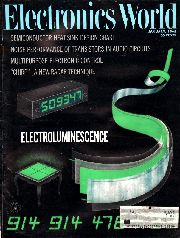
Decorative wall panel woven from colored strips of EL lighting
tape.
By Lester W. Strock, Ph.D. / Sylvania Electric Products Inc.
The cold light of electroluminescent devices is being put to ever increasing
use in home and industry. Here is the theory behind them coupled with an explanation
of how they are fabricated into various types of lamps and display items.
The phenomenon of electroluminescence (EL) has made possible the commercial development
of a true area cold light source. This has been a significant technological advance
- both in the lighting and display-device areas. In the lighting area, applications
are presently confined to those requiring brightness in the 0.5- to 100-footlamert
range. The impact of EL has been significant in the display-device field because
of the wide variation in sizes and geometrical shapes possible with EL. Individual
letters and numbers are available in sizes from 1/4" up. Special units of segmented
lamps, where the segments are combined at will by appropriate switching for forming
any letter or number, are commercially available for incorporating into larger information
display boards, such as airline information areas, for flight position markers,
ad computer-fed displays, for example, in financial market centers.
Electroluminescence is the phenomenon whereby light is emitted from a crystalline
phosphor (zinc sulfide in present lamps) placed as a thin layer between two closely
spaced electrodes of an electrical capacitor. One of the electrodes must be transparent.
The light output varies with voltage and occurs as light pulses more or less in
phase with voltage pulses. They are thus operated on a.c. with light output strongly
dependent on power frequency.
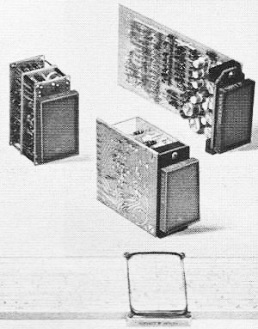
Solid-state modules designed to translate a four-bit binary code
to a numeric-type readout on the front-mounted EL panels.
Since performance of the lamps is determined primarily by the characteristics
of the phosphor, a detailed description of EL-phosphor properties and the electroluminescence
mechanism is essential to an understanding of the unique character of various types
of EL devices.
Photoluminescence in ZnS
The two chemical elements, zinc and sulfur, are familiar materials in science,
industry, and the home. Sulfur was known to the ancients, while zinc was first prepared
as a free metal in 1746. These elements readily combine to form a compound ZnS (zinc
sulfide), which occurs naturally as the mineral zinc-blends or sphalerite - a major
natural source of Zn (zinc) metal.
The addition of small amounts of certain metals to ZnS, as it is prepared in
the laboratory, converts this compound into a very important electronic and luminescent
material. ZnS is the host crystal for a large family of phosphors. When excited
by electromagnetic radiation of energy ranging from near-infrared wavelengths (2
microns) down to gamma rays, these phosphors emit light which collectively covers
the entire visible spectrum. Chemically, the color variations are achieved by progressive
substitution of Zn by Cd (cadmium) and of S (sulfur) by Se (selenium).
Essential, however, is the addition of much smaller amounts (0.0001-0.1% range)
of specific metals, of which Cu (copper) is a prominent and practical example, but
also including Ag (silver) and Au (gold) as "activators." Likewise useful as "co-activator"
is a halogen (prominently Cl, chlorine) or some normally trivalent material like
Al (aluminum), Ga (gallium), In (indium), or rare earths. Methods of preparation
also greatly influence the characteristics of a particular phosphor.
ZnS phosphors have been known for a long time for their response to cathode rays
as well as to 3650 Å ultraviolet excitation. An electron beam striking the
face of a vacuum tube coated with ZnS phosphor generates the visual image of its
path on oscilloscope, radar, and TV screens. Phosphate- and silicate-based phosphors
are used on the inner walls of fluorescent lamps where the exciting radiation is
of shorter wavelength (2536 angstroms in this particular case).
Electroluminescence in ZnS
G. Destriau reported excitation of zinc sulfide phosphors by an electric field
as a scientific phenomenon in 1936, but the light emitted was so faint that some
scientists cast doubt on the existence of the phenomenon. The first practical demonstration
of electro luminescence was given by Sylvania at the I.E.S. technical conference
in 1950. This clearly demonstrated that ZnS is a very important material having
both interesting and practical electronic and luminescent properties. Thus it is
that an increased knowledge of an old and previously used material like ZnS has
become the essential component in new solid-state light sources and devices.
It has been amply demonstrated that electroluminescence, as a phenomenon distinct
from photoluminescence, is dependent on some unique structural peculiarity of the
ZnS crystal, as well as its specific activator composition. This becomes evident
from the fact that the application of thermal and mechanical stresses can be quite
important in converting photoluminescent to electroluminescent phosphors. These
stresses produce strains within the crystal, forcing a rearrangement of its atoms.
For a brief review of the present theories of electroluminescence, refer to the
boxed copy on page 26.
Light Output of EL Phosphors
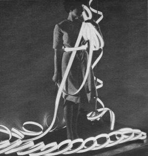
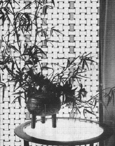
Flexible electroluminescent lighting tape can be made in lengths
up to 150 feet. Strip is 1/32" thick with lighted width of 1 1/8".
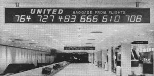
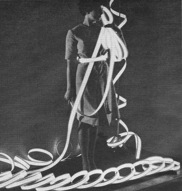
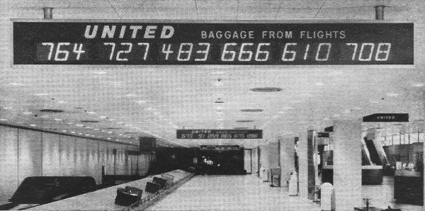
Electroluminescent numbers are used at O'Hare Field in Chicago
in order to identify flight numbers and arrival of baggage.

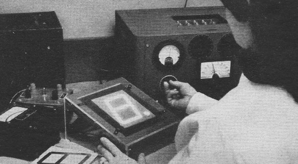
Initial testing of electroluminescent numeric readout element.
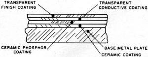
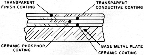
Fig. 1 - Example of five-layer, metal-ceramic construction.
The characteristics of EL phosphors are evaluated in the laboratory in demountable
cells. Such cells may present a square or circular lighted area of 2 to 3 square
centimeters. The viewing side is made of conducting glass plate which serves as
one electrode of the electric capacitor. The powdered phosphor (small crystals,
10- to 30-micron size) is suspended in some liquid dielectric, such as castor oil,
in a ratio of 1 cc. oil to 1 or 2 grams phosphor. The bottom electrode is made of
metal (brass or steel) in some convenient and substantial design so as to provide
a 3- to 5-mil spacing for the oil/phosphor mixture. Both electrodes are connected
to a variable frequency and voltage a.c. power supply. Voltages in the 50- to 500-volt
and frequencies in the 60- to 6000-cps range permit a thorough evaluation of phosphors
for both scientific and industrial purposes.
Light output can be measured with a photomultiplier detector and suitable current-reading
instrument. Evaluation of the commercially significant parameter of life must be
made on finished commercial products, as other factors also influence the life of
the device using EL phosphors.
Design of EL Devices
Unique features of EL lamps include: (1) their being an area light source, and
(2) their lack of catastrophic failure. Both features are responsible for their
special applications in areas of novelty lighting, instrument lighting, and the
broader field of display devices. Device applications make use of another feature
of EL lamps, namely their versatility in matters of size and shape. Being light
sources, their immediate function in whatever circumstances is to render something
visible. This may be accomplished by reflected light, in creating a silhouette,
or by its own luminosity. One thing is certain: an EL device is a solid-state light
source and, as such, be combined with other solid-state components to provide an
all-solid-state system. The fact that EL light is available from luminous areas
of a few square millimeters to a square meter or more, gives EL a broad application
range from tiny readout lamps to very large information display boards.
The actual construction of the EL lamp is determined by its intended application.
There are, at present, three types.
Metal-Ceramic & Glass-Ceramic Construction
The major application of the metal-ceramic construction is in lamps intended
as low-level light sources. Their essential components are shown in Fig. 1.
Present commercial products include: nighttime position markers (Nite Lites); switch
plates, luminous background advertising items; clock faces; telephone, radio, and
TV dials; automobile instrument panels; highway signs and markers; and decorative
panels (in a variety of colors) for walls, ceiling, and space dividers. This lamp
is of rugged construction and long life (in the neighborhood of 10,000 hours or
more when operated at 60 cps). It can be made to operate in the range of 50 to 1000
volts to produce surface brightness from a few tenths to 100 foot-lambert's. Most
current commercial units fall into these types: 120 volts, 60 cps yielding 1 to
1.5 foot-lambert's; 250 volts, 400 cps yielding 5 to 6 foot-lambert's, or 10- to
30-footlamberts range at 600 volts. By increasing voltage and frequency (e.g., 600
volts, 2000 cps), brightness in the neighborhood of 100 foot-lambert's results.
No lamp should be operated above manufacturer's ratings.
A. typical brightness-voltage characteristic is shown in Fig. 2. Increasing
the frequency will not harm the lamp, but unless rated for high-frequency operation,
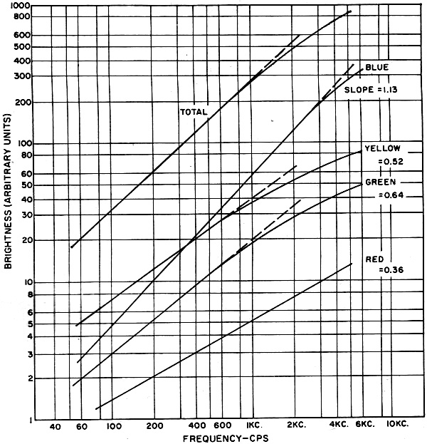
no spectacular increase in brightness may result. Fig. 3 illustrates, in the
case of a particular EL phosphor, the brightness at three different operating frequencies,
as well as the shift in color toward blue at higher frequencies. This is a result
of the more rapid rise of output by the blue component in a two-band (blue-green)
phosphor. Since phosphor life is closely proportional to operating frequency, obtaining
high brightness in this manner is at the expense of life.
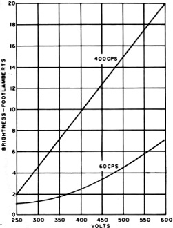
Fig. 2 - Brightness versus lamp voltage for a 600-volt EL
device. Note also how increasing excitation frequency raises brightness.
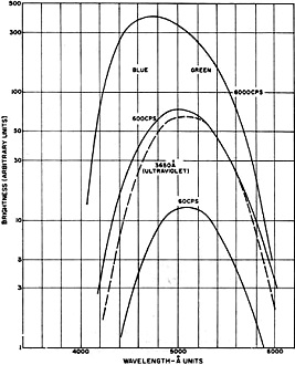
Fig. 3 - Effect of frequency on wavelength distribution
of the EL emission of a two-band phosphor peaking at 4600 and 5200 A.
The designation metal-ceramic refers to the use of an iron sheet as one electrode
and the ceramic (low-melting-point glass) phosphor embedment material in its construction.
A second ceramic layer can be placed between the iron plate and phosphor layer.
The second electrode should be transparent. It is applied in the form of a conducting
tin-oxide layer sprayed onto a thin glass layer over the phosphor layer, which is,
in turn, usually covered by a second glass layer for moisture, mechanical, and electrical
protection. Special spraying techniques for forming thin and uniform layers have
had to be developed by manufacturers of EL units, and for sintering glass frits
into transparent glass layers. The active phosphor layer of such lamps varies from
about 2 to 8 mils depending on rated operating conditions.
For space lighting applications, special blends of blue, green, and yellow phosphors
have been incorporated into lamps for producing various tones of white light. Fig. 4
shows the frequency response of such a white blend designed for 60-cps operations
(voltage affects color in only a minor manner).
The various slopes for the different color components, as described previously,
cause a decided color shift in emitted light when a lamp is operated at different
frequencies.
Besides the metal-ceramic makeup, glass-ceramic construction is also employed.
This is the construction favored for lamps used in display applications, since
it provides a flat surface for displaying information. In it, the active phosphor
layer is placed directly on the conducting surface of the glass plate without an
intermediate ceramic layer. This decreases the diffusion of light within the lamp
and leads to sharper readout patterns. Finally, the back electrode is advantageously
made of an evaporated metal film which adapts itself to segmentation for the purpose
of applying voltage to selected localized areas of the lamp. This is done by vaporizing
the back electrode through appropriate masks. These lamps are normally made to operate
at 250 volts and 400 cps to produce an over-all brightness of approximately 10 foot-lambert's.
Flexible Plastic Construction
In this type of construction (see this month's cover), the initial electrode
is again of metal; normally a thin aluminum foil. It is first coated with a thin
uniform layer of white high-dielectric material, followed by a mixture of phosphor
in a high-dielectric organic material which is converted to a tough plastic film
on baking at relatively low temperatures. The second electrode and light-escape
side of the lamp is a thin conducting glass paper cemented to the phosphor layer.
The entire EL unit is then sealed in a moisture and electrical protection envelope.
The assembly is approximately 1/32-inch thick, with a 1" to 5-mil separation between
electrodes. At 120 volts, 60 cps, this construction is a 5-footlambert light source
which increases to 30 foot-lambert's at 120-volt and 400-cps operation.
This construction is suitable for the production of lamps in long strips, in
widths up to 8 or 12 inches. A commercial version of this construction is the "Tape
Light," recently made available by Sylvania in 1 3/4-inch widths. The potential
application of this flexible lamp in lengths of many feet would seem to be great,
considering that it will take the shape of a variety of surfaces employed in contemporary
design and construction. Like the other lamp types, phosphors are available for
producing "Tape Lights" in a variety of colors (green, blue, white, yellow).
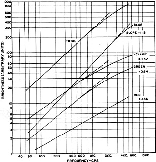
Fig. 4 - Light emission in different color bands of an EL
phosphor blended to produce white at 60 cps. Note frequency effect.
EL-Display Applications
The various types of construction just described may be used primarily for lighting
purposes, or in special device applications. In practice, the display applications
are at present largely confined to the glass-ceramic construction for reasons already
stated. There remains to briefly summarize the manner in which the operation of
lamps is altered, compared to their more simple use as light sources, when the intended
use is as a display. The problem is to convert the uniform area light into a field
of contrasting brightness so as to present a visual message to an observer or objective
detector. Basically, this means varying voltage across the active phosphor layer
from place to place in the lamp.
In practice, this means operating the lamp in localized segments at either of
two voltages, namely, at zero (or below threshold) and some finite value which will
excite electroluminescence. The "on-off" operation scheme is widely employed. The
mechanics of doing this are provided by appropriate segmentation and design of the
back electrode (metal film applied through masks). The problem is simple if a fixed
stationary display is the goal. But more important, EL devices make possible variable
displays. This adds complexity to their construction since various combinations
of component elements of a design must be selectively activated. This requires switching
of the operating power via wiring circuitry connected to thin metal films between
segments of, at times, very small areas.
The simplest variable display device is a seven-segment numeric readout, such
as the one shown in Fig. 6A. This is commercially available to give numbers
ranging in size from 3/8" to 8" in height. Connecting these seven segments electrically
(via the back electrodes of the lamp) in various combinations forms all numbers
0 through 9. This simple arrangement of segments cannot center the digit "1." In
order to center the digit "1,"a 9-segment device is available (Fig. 6B) which
can be operated as an 8-segment lamp. The switching arrangement is only slightly
more complicated.

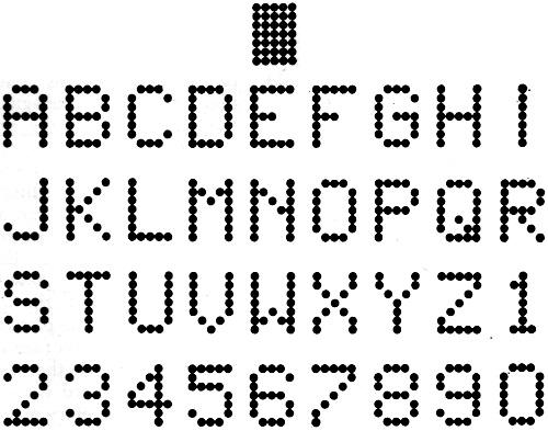
Fig. 5 - A complex display pattern using 35 dots in a 7
x 5 array can be used to produce a complete set of alphanumerics.
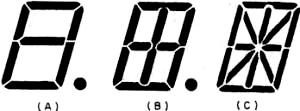
Fig. 6 - (A) Seven segment readout, (B) nine segment readout,
and (C) 14 segment readout. These are alphanumeric displays.
A far greater range of readout applications is provided by a 14-segment lamp
(Fig. 6C) with which letters of the alphabet as well as digits can be displayed.
This is the familiar alphanumeric readout. The added segments, however, substantially
increase the switching, electrode contacting, and connecting problems. By increasing
the number of segments and changing from rectangular to circular segments, more
aesthetically pleasing number and letter displays are obtained. The familiar 35-dots-per-letter
in a 5 x 7 array is the best-known example. Others have been developed. The practical
problems become formidable with these multi-segmented lamps, both in circuitry,
switching, and in applying the segmented electrode itself. Display units have been
developed which carry several numerics on one lamp. This provides space economy,
reduces hardware, and provides clearer viewing.
Fig. 5 shows the complex alphanumeric pattern using the 35-dot 5 x 7 array,
along with a sample of the display obtainable by its use. Increased visibility of
display is possible by use of neutral gray (60-70% transmission) glass in the lamp.
Surface reflections are reduced by application of anti-reflection coatings to the
glass. The use of a glass-surface lamp makes it possible to apply a honeycomb filter
for purposes of reducing the effect of high ambient light. This, however, restricts
the viewing angle to approximately 30°, but makes it possible to use it in sunlight.
The switching component requirements of EL-display devices depend on the speed
demanded by the application. Mechanical switching is employed in electronic accounting
and scaling equipment and in production-line status boards. For more rapid switching
requirements and in conversion of intelligence from a computer, electronic switching
is employed through the use of silicon controlled rectifiers, neon-photoconductors,
reed switches, and transistor circuits.
With the versatility in size, geometrical form of information display elements,
and switching speeds now available, the possible applications of EL-display devices
seem almost unlimited.
Producers of EL devices naturally stimulate those interests by continued assistance
and developments. Efforts are continually being made to develop phosphors and lamp
structures which will substantially increase the brightness of present EL light
sources, so that lamps may eventually be as bright on domestic power operation as
now obtainable at higher voltages and frequencies. Brightness up to 100 foot-lambert's,
sufficient for ceiling and wall panels incorporated into the architectural structure,
are not unrealistic expectations to those engaged in product development, and perhaps
more so to those of us in basic research.
Review of Present Theories of Electroluminescence
A ZnS crystal consists of alternating layers of zinc and sulfur atoms. Much lower
fields (factor 10 or more) are required to produce light when the field is applied
parallel to these layers. Since high conductivity also exists parallel with the
"easy" EL direction, light emission in this direction is evidently dependent on
the flow of external electrons. In the perpendicular direction (called the c-axis)
light emission involves displacement of electrons already present in the crystal.
An EL crystal thus seems to emit light by two mechanisms: (1) low-field/high-current
for a field parallel to atom layering or perpendicular to crystal c-axis, and (2)
high-field when the field is perpendicular to the layering.
This directional dependence or anisotropy (different properties in different
directions) has been explained by the author as resulting from an isolated atom
displacement disorder. Such a disordering of the otherwise regular repetition pattern
of Zn- and S-atoms of the ZnS crystal causes a sulfur atom to move under the influence
of local strains into a nearby and alternate (but unoccupied) position of the crystal
lattice. As a result, a covalent chemical bond (electron pair) by which this displaced
sulfur atom was attached to one of its normal four Zn-atom neighbors has been broken.
The geometry of the immediate site, after creation of this disorder, is such that
a single charged copper ion (Cu+'-ion) can be exactly fitted into the space next
to the broken band on the displaced S-atom. This "quasi"-free Cu+1-ion
restores a more normal local energy situation.
This seemingly trivial matter of moving an isolated S-atom for a very short distance
of about 4 A (angstroms) to a neighboring site, followed by entry of a Cu+1-ion
adjacent to it, provides a model useful far developing the details of a light-emission
mechanism from an entirely different viewpoint than previously attempted.
Energy-Band Model
ZnS crystals are typical "wide-band-gap" semiconductors, and previously proposed
theories have been based largely on energy-band-gap models. The band gap of ZnS
is 3.76 electron volts (ev.). This means that energies of this amount are required
to excite electrons associated with atoms on lattice sites of the crystal (valence
band) to the conduction band where they may move for a very short time about the
crystal as "conducting" electrons. Activators in a ZnS phosphor add new levels in
the "forbidden" gap of ZnS at levels up to 1 ev. above the valence band. Since light
absorbed by the activators is normally of shorter wavelength (higher photon energy)
than that emitted, the phosphor has served as a wavelength or color converter. In
the case of the ZnS:Cu-Cl EL phosphor most widely used, absorption of 3650 A leads
to emission of two wide bands: the blue peaking at about 4600 A and the green peaking
at about 5200 A. These represent electron transitions of 2.70 and 2.4 ev. between
activator levels and trap levels a few tenths of an electron volt below the conduction
band.
Collision-Ionization Theory
Although satisfactory for the description and calculation of photoluminescence
phenomena, the energy-band model has not been able to treat all of the features
of electroluminescence. Mainly there is the question of how the energy of the electric
field, applied to lamps at levels of 50 to 100 volts per mil, is transferred to
the phosphor to cause light emission. Even if the prime characteristic of electroluminescence
is just a special mechanism for triggering off photoluminescence which then proceeds
via the collision-ionization mechanism commonly accepted in electroluminescence
theory, the question of the source for initial electrons remains. They do not seem
likely to be created by direct-field ionization of luminescence centers because
this will require fields acting on individual Cu activator atoms, e.g., to produce
blue emission, in excess of that generally available by a factor 2280 in case of
a 1-mil-thick device operated at 120 volts. To produce blue emission, energy in
excess of 2.7 ev. must be applied across a Cu-atom of 2.7 A diameter representing
a field of 1 volt/A or 108 volts/cm. The available field is actually only 4.4 X
10-4 volt/A. Concentrating the 120 volts available into a very small
fraction of the active layer thickness; e.g., 120 A will produce a field adequate
for direct ionization for purpose of supplying the initial electrons, which are
then accelerated to velocities sufficient to collision-ionize other centers. The
assumption of the existence of such barriers has been a prominent feature of previous
EL theories. The field-release of electrons from donors or from traps a few tenths
of a volt below the conduction band has been proposed in order to account for the
release of electrons at low values of field intensity.
Atom-Ion Pair Model
It is also possible to explain the above-mentioned anisotropy of EL emission
by the isolated atom displacement model. Its essential feature is that in the EL
center there exists an atom-ion pair oriented with its join line perpendicular to
crystal c-axis. EL emission results when an electron oscillates between the atom
and ion in phase with an a.c. field.
The extent to which this electron exchange process produces light directly by
optical transitions and indirectly by virtue of furnishing electrons which escape
the center into the surrounding host crystal, where on acceleration they ionize
normal photoluminescence centers, is still unknown. Assuming the essential correctness
of the EL-center model, the chemical entity of the atom-ion pair will determine
the color of EL emission. If some electrons escape from the center to trigger off
the characteristic photoluminescence of the host crystal, the light emitted will
be a composite of the output of the two mechanisms involved.
EL and Photoluminescence
The close similarity of some bands of light emitted by an EL phosphor under ultraviolet
light and field excitation has long been a point of interest which, on the basis
of the model, indicates that a substantial portion of electrons from the center
do escape to the surrounding crystal, especially at low frequencies. However, as
frequency increases, the number of electrons escaping the center will decrease,
confining. light emission more and more to the primary EL mechanism, with less from
the host crystal. That this does happen receives support from the known frequency
characteristics of the widely used blue-green ZnS:Cu-Cl EL phosphor. Here, the blue
component emission increases steadily with frequency and at a much faster rate than
does the green component. Further, green emission soon reaches a plateau. In line
with the theory, the blue component is the prime EL emission generated by the EL
center; while green is photoluminescence originating at luminescence centers of
the surrounding crystal.
Attempts to convert yellow photoluminescent phosphors to EL phosphors have revealed
that frequently any EL emission created is blue. Most EL yellow phosphors contain
a blue component. In this case, electrons do not escape to yellow centers in the
surrounding crystal. The study of EL phosphors in the laboratory is thus a very
essential step in the development of commercial EL lamps.
Posted September 21, 2021
(updated from original post on 2/27/2014)
|