|
July 1965 Electronics World
 Table of Contents
Wax nostalgic about and learn from the history of early electronics. See articles
from
Electronics World, published May 1959
- December 1971. All copyrights hereby acknowledged.
|
The July 1965 issue of
Electronics World magazine contained articles on many types of capacitors
being used at the time. As of this writing I have posted the articles on paper
and plastic film capacitors. Still to come are mica, ceramic, and glass. Newer
dielectric formulations have been developed since then, with some being
improvements on existing types and others being either rarely or never used back
then. Notably missing in the capacitor formats are distributed element on
substrate, semiconductor, and air (vacuum). Construction and parameters for both
polarized and non-polarized electrolytic capacitors are addressed by Mr. H. Nieders, of the
Mallory Capacitor Company (now
Duracell).
Electrolytic Capacitors
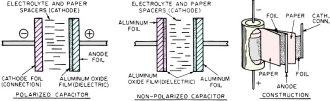
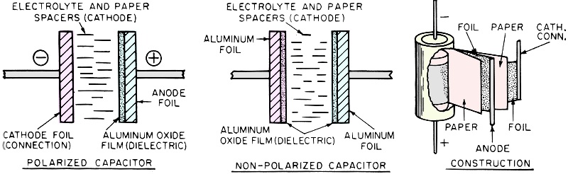
Fig. 1 - Cross-section of (A) polarized and (B) non-polarized
aluminum electrolytics. (C) shows the construction details.
By H. Nieders
Mallory Capacitor Co., Div. of P.R. Mallory & Co., Inc.
Widely used where large capacitance and small size are required, electrolytics
are among our most important capacitor types. Aluminum and tantalum units are covered.
In 1964 some 2,305,000,000 units of all types of capacitors were produced and
sold. Of this total, electrolytic capacitors accounted for 249,000,000 units. In
terms of dollars, this amounted to about $344,000,000 for all capacitors and $127,000,000
for electrolytic types. These figures would seem to indicate that electrolytic capacitors
are expensive - but this is not true.
Electrolytic capacitors actually save money, space, and weight when used properly
within their limitations and the limitations of the circuitry employed. The "why"
of electrolytic capacitors is economy; the "when" is a matter of application.
Generally, electrolytic capacitors can be divided into two basic types by the
nature of the base-oxidizable metal used. This is usually either aluminum or tantalum.
There are other usable metals, but these two yield relatively large capacitance
per unit of volume at an economical price. A tantalum capacitor costs more money
but saves more space and weight than an aluminum unit. There are other technical
differences, but the two types are more easily understood when reviewed separately.

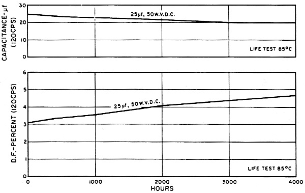
Fig. 2 - A typical life test for one specific type of industrial-grade
can-type aluminum electrolytic with axial leads.
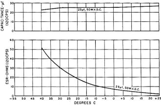
Fig. 3 - Typical stability of electrical characteristics vs.
temperature for same type of industrial-grade capacitor.
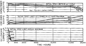
Fig. 4 - Typical life test for one particular type of premium-grade
can-type aluminum electrolytic unit with axial leads.
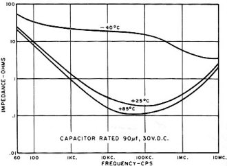
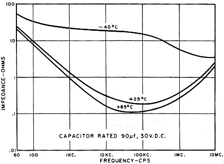
Fig. 5 - Typical impedance vs. frequency at various temperatures
for same type of premium-grade can-type aluminum electrolytic.
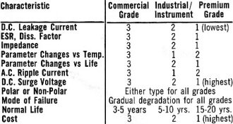
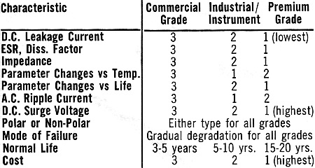
Table 1 - Ranking of some of the more important characteristics
of the three major types of aluminum electrolytic capacitors.
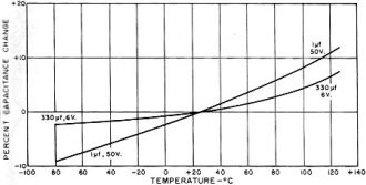
Fig. 6 - Typical capacitance change with temperature for one
specific type of solid-electrolyte tantalum electrolytic.

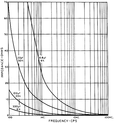
Fig. 7 - Impedance change vs. frequency measured at 25°C for
the same type of solid-electrolyte tantalum capacitor unit.
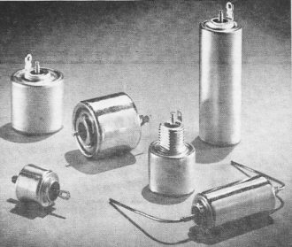
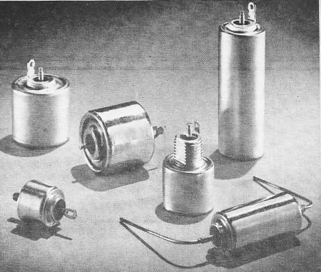
Grouping of special radiation-resistant tantalum electrolytics.
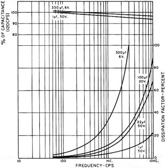
Fig. 8 - Typical capacitance and dissipation factor changes with
frequency at 25°C for same type of tantalum capacitor.
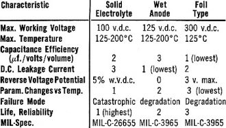
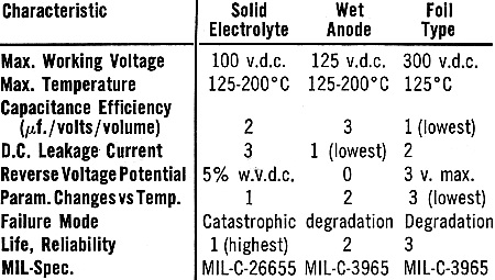
Table 2 - Ranking of some of the more important characteristics
of the three types of tantalum electrolytic capacitors.
Aluminum Electrolytics
Fig. 1 is a simplified representation of an aluminum electrolytic capacitor.
Both polarized and non-polarized types are shown. Normally a piece of aluminum foil
is etched to increase its surface area, then it is treated electro-chemically to
form aluminum oxide on its surface. The oxide is the dielectric of the capacitor
- the thickness of this oxide determines the voltage rating. Since this oxide film
is so thin and the surface area of the electrodes is so great, the capacitance produced
is very large.
Paper spacers are applied next to the aluminum oxide surface. These spacers prevent
direct shorts between anode and cathode foils. Thus, for higher voltages, more and
thicker spacers are used. The spacers also absorb the electrolyte, allowing it to
be retained in the correct place and providing intimate contact with the surfaces
of the anode and cathode foils as required for proper operation.
The cathode foil serves only as an electrical connection to the electrolyte.
The electrolyte is the true cathode and it has the ability to oxidize any imperfections
in the aluminum oxide dielectric.
Non-polarized capacitors use two anodes and have one-half the capacitance of
an equal-size polarized unit of the same voltage rating.
When electrolytic capacitors are used as energy-storage devices where the load
resistance is small compared to load inductance, current reversals may occur for
a short time. Accordingly, the voltage will reverse for the same time, making the
use of a non-polarized unit mandatory. Electrolytics for a.c. motor starting and
for audio cross-over networks should be non-polarized types. It is also wise to
consider using a non-polarized unit where large pulse signals are encountered. For
most applications, however, electrolytics are used across a d.c. voltage so that
the ordinary polarized units are employed. The designer must avoid voltage reversals
on polarized units.
Leakage Current and ESR
All electrolytic capacitors allow a small amount of d.c. leakage current to pass
through when rated polarized d.c. voltage is applied. This current will go up with
rising temperature and voltage. In general, the amount of leakage current is indicative
of the immediate quality of an electrolytic capacitor - the lower the better. Long
shelf life or storage will cause the leakage current to go up. Leakage can also
be detected by the time it takes to charge the unit to rated d.c. voltage.
ESR (equivalent series resistance) is a measure of the internal resistance of
a capacitor. This resistance is responsible for the heating effects associated with
a capacitor. The ESR of an electrolytic varies inversely with temperature. It is
also related to capacitance and frequency.
The dissipation factor (D.F.) of a capacitor is the ratio of the ESR to the capacitive
reactance. The power factor (P.F.) is the ratio of the ESR to the total impedance
of the capacitor. For low losses, power factor is equal to dissipation factor up
to 12%. Beyond this, dissipation factor increases without limit as losses go up.
Naturally, as the capacitor deteriorates, the ESR increases. If all these factors
are taken together, it can be concluded that ESR is a most important factor when
judging a capacitor for its use and end-life characteristics.
ESR also has an effect on the ripple-current rating of an electrolytic capacitor.
The a.c. ripple current combined with the ESR causes internal heating which must
be dissipated. A small additional loss caused by the d.c. leakage current is also
present, but is usually negligible.
A rule-of-thumb for determining maximum permissible ripple current conditions
is that the capacitor case temperature shall not exceed + 10°C above the maximum
rated temperature for the capacitor. It is also common to allow a 5°C increase
in case temperature rise for each 10°C decrease in ambient operating temperature.
Variations and Types
The capacitor designer can vary the cost, life, electrical parameters, temperature
range, and mechanical factors by changes in anode foil, cathode foil, paper spacers,
electrolytes, terminations, and packaging.
For example, using an anode with a high ratio of formation voltage to rated capacitor
voltage in combination with heavy paper separators and a conservatively activated
electrolyte (close to neutral ph), will result in a capacitor having long life,
-20 to +65°C temperature range, and medium changes in electrical parameters.
The choice of packaging can affect even this conservatively designed unit. Generally
the package can be judged by its ability to keep the electrolyte from escaping,
leaking, or diffusing from the container. The better the package is sealed, the
better the capacitor will retain its initial characteristics.
Capacitors are made and sold by intended end use in three grades: (1) commercial,
(2) industrial/instrument, and (3) premium. The commercial generally offers the
most capacitor for the lowest price. The industrial/instrument is a conservatively
designed capacitance section in the lowest priced package. The premium grade is
the finest capacitance section and best package for optimum electrical performance
in all respects.
Within each of these three categories, the manufacturer offers a very large variety
of sub-types that differ from each other in certain characteristics and applications.
Table 1 generalizes the importance of the various characteristics and ranks them
for the three main grades of capacitor. In addition, Figs. 2, 3, 4, and 5 show some
of the important characteristics of two specific types of aluminum electrolytics,
one in the industrial/instrumentation grade and one in the premium grade.
Tantalum Electrolytics
Tantalum is the second most popular oxidizable-base metal for use in electrolytics.
Tantalum oxide has almost twice the dielectric constant of aluminum oxide and is
exceptionally stable with temperature. It is also very inert to chemical attack
and this property allows the use of highly ionized acid electrolytes not possible
with aluminum. Tantalum is available in a high-purity form both as a foil and a
powder, thus more diverse physical arrangements are possible than with aluminum.
All these properties of tantalum make it possible to produce tantalum capacitors
with these advantages: higher μf./volt per unit volume, wider operating temperature
range, better temperature stability characteristics, longer life, more rugged construction
features, better electrical parameters, and excellent shelf life. The main drawbacks
are the greater cost and the lower operating voltages of the tantalum types.
Of all the plus features, the stable shelf life at temperatures of 30-40°C
for periods of time up to 5 and even 10 years without harmful parameter changes
is the most outstanding. This factor alone makes it possible to use electrolytics
widely in military gear. Thus, the expense of this rare metal was justified and
has led to the almost explosive development and use of several types of tantalum
electrolytics in the past ten years. In 1964, for example, 64,000,000 units, worth
$51,000,000, were sold.
Three major categories of tantalum electrolytics are being made and used in quantity.
They are the solid electrolyte types, foil types, and wet anode types with solids
outselling the other two by a ratio of 5 to 1 or more.
The tantalum foil types are similar in construction to the aluminum electrolytics.
The oxide on the anode foil is the dielectric, the electrolyte is the cathode, and
the cathode foil is primarily a connector. They are cased in aluminum with various
end seals made of rubber or Teflon. Generally, the package construction is more
critical because of the emphasis on long life and stable electrical parameters for
high reliability end use.
Wet-anode styles are made by pressing tantalum powder and a binder, in a mold
or die, to a given shape, usually cylindrical. These pellets are then sintered under
high vacuum and temperature to remove the binder and impurities, leaving a rugged,
porous metal pellet which is then electro-chemically treated to form a layer of
tantalum oxide. These anodes are then assembled in silver outer cases, filled with
an electrolyte, and sealed. Again, a rubber or Teflon end seal or a combination
of both are used to achieve a nearly hermetically sealed container.
Solid-electrolyte units are made by using a sintered anode which has an oxide
formed on it the same as that used for wet-anode types. The porous anode is then
impregnated with a liquid solution of manganous nitrate which is then fired in an
oven and converted to manganese dioxide. This semiconductor material is the solid
electrolyte and true cathode of the capacitor. A layer of carbon followed by a layer
of silver paint completes the cathode connection. This complete capacitor is then
soldered in a tinned metal container and a glass-to-metal seal affixed to the positive
end. Thus we have a rugged, hermetically sealed package with no liquids to leak
out.
A brief comparison of these three types of capacitors is given in Table 2. The
characteristics are ranked numerically for brevity and ease of interpretation.
A thorough and detailed description of all three styles, along with a quality-control
plan and much information on test techniques is available in the MIL-C Specs listed
in the table. These MIL-Specs are widely used as industry standards and many suppliers
are qualified to furnish products which meet these specifications. All major manufacturers
also have special designs and lines in addition to the Military types.
The graphs shown in Figs. 6, 7, and 8 illustrate typical characteristics of a
solid-electrolyte tantalum electrolytic capacitor.
Posted September 9, 2022
|