|
July 1965 Electronics World
 Table of Contents
Wax nostalgic about and learn from the history of early electronics. See articles
from
Electronics World, published May 1959
- December 1971. All copyrights hereby acknowledged.
|
The term "metallized dielectric"
at first might seem like an oxymoron. After all, if you add a conductive substance
to the dielectric of a capacitor, then you have compromised the integrity of the
dielectric as a non-conducting substance. Here's the deal: The dielectric material
between the conductive plates does not receive the metallization; a non-conductive
(dielectric) material like paper is impregnated with metal and that is used for
the plate material. The advantage of this scheme is that the plate material
can be thinner, thereby reducing the size of the capacitor package for a given capacitance
value. It comes with a price, of course, and that is a lower operational and maximum
applied voltage rating. With proper design in circuits like power supplies, metallized-dielectric
capacitors can facilitate great space savings. A major benefit of metallized-dielectric
capacitors is an ability to
self-heal when the plate material develops a short circuit through the dielectric.
Metallized-Dielectric & Standard Capacitors
Capacitor Value Change over Temperature
The use of metallized paper, film, and dual dielectrics normally results in a
capacitor much smaller than foil-type capacitors of comparable rating. In some cases,
a volume savings of up to 75% may be realized by the selection of a metallized dielectric
capacitor. The small size and self-healing properties of metallized dielectric capacitors
make them an ideal choice in many applications.
The advantages of metallized capacitors, however, cannot be utilized in all situations.
Metallized capacitors are not recommended for coupling applications, logic circuits,
or other applications where occasional momentary break-downs and periods of low
insulation resistance (sparking and subsequent self-healing) cannot be tolerated.
The maximum value of the a.c. component that may be applied to the capacitor is
limited by both the test voltage rating and by the limited heat conductivity of
the thin metallized surfaces. Instantaneous surge voltages must not exceed the maximum,
or sparking, voltage rating of the capacitor.
Metallized capacitors are widely used in power-supply filter circuits, bypass
applications, and decoupling and smoothing applications where low impedance is required.
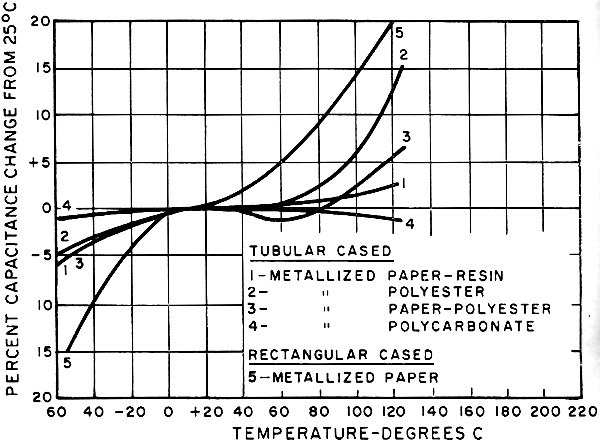
The graph illustrates the capacitance-temperature characteristics of paper, polyester,
polycarbonate, and paper-polyester metallized dielectrics and metallized combinations.
Standard Capacitors
A properly designed air capacitor approaches the ideal standard reactance in
that it has very low loss and very small changes with time, frequency, and environment.
Capacitance changes with atmospheric pressure and relative humidity can be eliminated
by hermetic sealing. Changes with temperature can be eliminated by the use of low
temperature coefficient materials in the capacitor.
For values above 1000 pf., solid dielectrics are used. The preferred dielectric
is high-quality mica because of its dimensional stability, low loss, and high dielectric
strength. At d.c. or extremely low frequencies, the mica dielectric has the disadvantage
of relatively large change of capacitance with frequency as a result of dielectric
absorption caused by interfacial polarization in the dielectric. Polystyrene, on
the other hand, has a dielectric constant and dissipation factor very nearly constant
with frequency, so that capacitance change from d.c. to 1 kc. is a small fraction
of a percent instead of the 3% drop at 1 kc. typical of mica. However, the temperature
coefficient of a polystyrene capacitor is on the order of -140 PPM°C.
Uncertainties in the calibrated value of a two-terminal capacitor can be on the
order of tenths of a pf. if the geometry, not only of the capacitor plates, but
also of the environment and of the connections is not defined and specified with
sufficient precision. For capacitors of 100 pf. and more, the capacitance is usually
adequately defined for an accuracy of a few hundredths percent if the terminals
and method of connection are specified. For smaller capacitances, or higher accuracy,
a two-terminal is seldom practical and a three-terminal unit is preferred.
A three-terminal capacitor has a shield that completely surrounds at least one
of its terminals, its connecting wires, and its plates, except for the area that
produces the desired direct capacitance to the other terminals. Changes in the environment
and connections can vary the terminal capacitance but the direct capacitance is
determined only by the internal geometry.
The direct capacitance can be made as small as desired since the shield between
the terminals can be complete except for a suitably small aperture. The losses in
the direct capacitance can also be made very low because the dielectric losses in
the insulating materials can be made a part of the terminal impedances. When a three-terminal
capacitor is connected as a two-terminal device, the two-terminal capacitance will
exceed the calibrated three-terminal value by at least the terminal capacitance.
Although the characteristics of the high-quality capacitors used as standards
closely approach those of the ideal capacitor, any deviations from ideal performance
must be evaluated to obtain the necessary high accuracy.
Posted September 28, 2022
|