|
May 1963 Electronics World
 Table of Contents
Wax nostalgic about and learn from the history of early electronics. See articles
from
Electronics World, published May 1959
- December 1971. All copyrights hereby acknowledged.
|
Capacitor science has evolved
at a very rapid rate since the beginning of electronics and electrical circuitry.
Since the early
Leyden jar (named after the city where it was invented
by Ewald Georg von Kleist) type capacitor, continual advancements in materials
for electrolytes and metal plates, as well as in packaging, have led to incredibly
high storage density, miniature size, high voltage and current, mounting configuration,
low ESR, high frequency operation, price, stability, temperature extreme tolerance,
and other parameters. It is always instructive and interesting to read the history
that has led to the current state of capacitor art. This 1963 Electronics
World magazine article does just that.
Modern Capacitors
By John R. Collins
Spurred by the sophisticated needs of electronics today, developers
have endowed an old, familiar component with variety and capabilities not anticipated
years ago.
Although capacitor development reached a highly advanced stage many years ago,
the exploitation of all possible combinations of materials and configurations did
not end. As electronic applications grow, the demands made of conventional components
also expand. Manufacturers then reach into their accumulated store of know-how for
the answers to new problems. After a few years of such stimulation, an "old" product
can take on quite a new look, even without revolutionary design changes.
Current requirements for military and space programs and for complex industrial
equipment are placing heavy demands on capacitor producers. High-temperature operation
has become increasingly important, for example, and the effects of radiation must
be reckoned with. Such factors have led to the production of capacitors that are
quite special, although they may end by finding widespread application. The units
in Fig. 1, to cite a case, are practically indestructible under the severest
environmental conditions. Size and weight are of prime importance for airborne and
space use, so special emphasis is placed on types with maximum capacitance per unit
volume (Fig. 2).
Many materials now used are not very different from those employed in the past.
Each, however, is now being perfected to the limits of its capabilities, so that
even traditional paper and foil capacitors now meet specifications unknown years
ago - and modern glass capacitors bear little resemblance to the ancestral Leyden
jars!
On the other hand, there are many developments that are still in the laboratory
stage. These include high-temperature dielectrics for use up to 750° C (almost
1400° F), thin-film dielectrics deposited on silicon slices (an outgrowth of
recent semiconductor technology), printed tantalum/tantalum-oxide types, and microscopic
RC combinations to serve as integrated networks and circuits.
Basic Factors
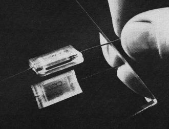
Fig. 1. These monolithic, glass dielectric types produced by Corning can
withstand severe environmental conditions.
Although a capacitor can be defined simply as a device for storing an electric
charge, it may be used to perform one of many functions in electronics, These include
passing a.c. while blocking d.c., bypassing r.f. to ground, filtering ripple from
rectified voltages, correcting phase angle, and being part of a resonant circuit.
Each application makes different demands, and the variety of types has grown out
of these needs. To clarify them, a preliminary review of fundamentals is helpful.
A capacitor is formed whenever two conductors are separated by an insulator.
The amount of capacitance depends on the areas of the two conductors, the distance
between them, and the material used for the insulator. For maximum capacitance,
the conductor plates are made as large as possible and the separation as small as
possible. Practical limits are set on the size of the conductors by space requirements;
yet, if the separation is very small, the danger of arcing is increased.
The merit of the insulator, called the dielectric, is measured with respect to
air. Air has a dielectric constant (designated by K) of 1. Other substances with
higher dielectric constants permit greater capacitance to be obtained for plate
areas of the same size and spacing. Certain mica, for example, has a K of 9, and
therefore two plates separated by it would exhibit 9 times the capacitance they
would have when separated by an equal thickness of air.
Capacitance normally undergoes a change with a variation in temperature. The
temperature coefficient is expressed conveniently as so many parts per million per
degree centigrade (ppm ° C). It may be either positive or negative, depending
on whether the capacitance increases or decreases with temperature.
A perfect type would introduce only capacitive reactance into a circuit, but
every capacitor is bound to have some resistance in which power is dissipated. The
merit of a capacitor, expressed in terms of the ratio of its resistance to its total
impedance, is called its power factor. Merit is also stated at times in terms of
the capacitor "Q," which represents the ratio of the capacitive reactance to the
equivalent series resistance. For all practical purposes, "Q" is considered to be
the reciprocal of the power factor.
Paper and Film Capacitors

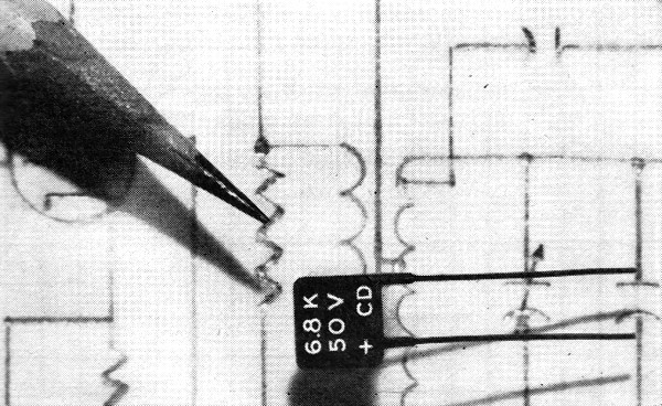
Fig. 2. This rectangular, solid-tantalum capacitor, made by Cornell-Dubilier,
concentrates 6.8 μf. at 50 volts into a package so tiny as to be dwarfed by the
average fingernail.

Fig. 3. They look like ordinary molded tubulars, but the
dielectric is made of a thin film of Mylar. This type (these made by Erie Resistor)
is being used in numerous applications.
Perhaps the most familiar type is the paper capacitor, which is made by rolling
two strips of aluminum foil, separated by paper, and attaching leads to the foil
strips. The unit is then encapsulated in anyone of a number of ways to make it moisture
resistant.
Kraft paper in extremely thin sheets, made from wood pulp, provides. a superior
dielectric now almost universally used. When impregnated with mineral oil, it gives
good temperature stability and a low power factor. Since very thin sheets usually
have pinhole defects, it is customary to use at least two sheets for the dielectric.
The chance of two defects occurring at exactly the same place is relatively slight.
Additional sheets may be inserted to increase the voltage rating of the capacitor.
In recent years, various plastic films have been used instead of paper for dielectrics
(Fig. 3). They can be made extremely thin without danger of pinhole defects,
and some
have special properties that are otherwise desirable. Polystyrene, for example,
has a remarkably small power factor and a very low temperature coefficient, while
Teflon can be used at temperatures as high as 250° C. Mylar film as thin as
0.00015 inch, now in use, permits substantial reduction in capacitor size as well
as an extended temperature range. Work is also progressing on combining two films
with complementary temperature characteristics (e.g., Mylar and polystyrene) in
the dielectric to obtain a virtually flat temperature-capacitance curve.
Miniaturization has been greatly advanced by the process of vacuum-depositing
metal in a thin layer on the surface of paper or film, thus eliminating the heavier
aluminum foil normally used as plates. Metalized-paper and film capacitors also
give a higher degree of reliability than conventional foil types.
This is so because a common cause of failure in paper and film capacitors is
the breakdown of dielectric due to high-voltage puncture. When this happens, the
two foil strips are brought into contact with each other and the capacitor is shorted.
When arcing occurs in a metalized capacitor, however, the metal burns away with
the paper or film at the puncture, so no short occurs: The capacitor is as good
as ever, except for an almost imperceptible reduction in its capacity. Such types
are called "self-healing."
Glass Dielectric
First developed as substitutes for mica types, glass-dielectric capacitors have
reached so high a level of reliability that they have won an important place in
missile and space programs. They have been boiled in salt water, immersed in saturated
steam, subjected to many hours of salt spray and many days of moisture tests without
failure or measurable degradation of their characteristics.
A special lead-potash glass with a K of about 6, used for the dielectric, is
rolled into a ribbon approximately 1 mil thick (Fig. 5). The basic construction
involves interleaving layers of glass ribbon and aluminum foil to provide the active
area, as shown in Fig. 4. Dumet leads welded to the aluminum foil provide glass-to-metal
seals. The case is made of the same glass as the dielectric, and the entire assembly
is then fused with pressure and heat to form a single block containing the capacitive
element.
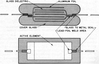
Fig. 4. Construction details of a glass-dielectric type, in side and top
views. Compare with actual sample in Fig. 1.
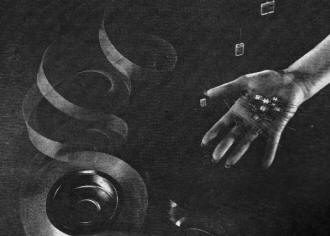
Fig. 5. Thin ribbons of glass (left) are used to form the dielectric of
capacitors like those in the hand at right.
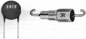
Fig. 6. Disc ceramic types offer high capacitance relative to size. Values
are affected by thermal and voltage changes (left).
Fig. 7. A feedthrough ceramic for bypassing r.f. to ground (right).
Glass capacitors are ordinarily made in a range of values from 0.5 to 10,000
pf. (μμf.). They are generally rated for 300 to 500 d.c. working volts, and
for a temperature range of -55° C to 125° C.
Since the cost of glass capacitors is higher than of mica varieties, they have
little application in the entertainment field. They are used most frequently for
military and certain critical industrial equipment.
Ceramic Capacitors
A number of ceramic dielectric materials have been developed with K's ranging
from 10 to 10,000. These include titania, barium titanate, stannate, and zirconate.
They provide a high capacity-to-volume ratio plus other interesting features.
Normally, a ceramic capacitor is made with a small sheet of ceramic material
that has been silvered on both sides, Wire or ribbon leads are applied to this sheet,
and the unit is enclosed in an insulated case. Where more capacitance is desired
in the same area, units are made with 2, 3, and 5 ceramic sheets. The most common
kind of ceramic capacitor is shown in Fig. 6. However, they are designed in
a number of configurations for special applications. Fig. 7 shows a feedthrough
capacitor intended for mounting on a chassis, where it serves as a stand-off insulator
for attaching other components and also for bypassing r.f. to ground.
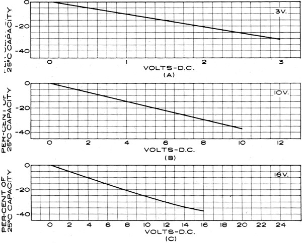
Depending on the mixture of elements, ceramic capacitors exhibit large changes
in capacitance with both voltage and temperature. Typical capacitance-voltage and
capacitance-temperature curves are shown in Figs. 8 and 9. Both characteristics
have been utilized for electronic circuits. Voltage-sensitive capacitors with barium
titanate dielectrics are used for one kind of parametric amplifier and for special
circuits where a voltage change varies the resonant frequency of a tank circuit.
Ceramic capacitors which are capacitance-sensitive to temperature in varying,
predetermined degrees have found wide application in tuning and resonant circuits.
They are sometimes used in FM receivers, for instance, to maintain resonant circuits
at a constant frequency and thus prevent drift during warm-up, by compensating for
temperature-induced changes in coils and other circuit elements.
Electrolytic Capacitors
The greatest capacity per unit volume is provided by electrolytic capacitors.
Although they have very large power factors and considerable leakage conductance,
these factors are not important for many applications. Certain metals, especially
aluminum and tantalum, are readily coated with a film dielectric by an electrochemical
forming process. Aluminum electrolytic capacitors are made by placing gauze saturated
with a highly viscous or fudge-like solution of aluminum borate between two strips
of aluminum. The strips are then wound into a roll and placed in a suitable container.
When d.c. is passed through this assembly, a thin film of aluminum oxide forms on
the anode strip. This film serves as an insulated dielectric and current drops rapidly.
The cathode strip is not similarly affected.
It is important to note that the cathode strip serves only as a contact with
the electrolyte, and that it is the oxide film, not the saturated gauze, which serves
as dielectric. This film has a high dielectric constant and is capable of withstanding
considerable voltage.
The depth of the oxide coating is determined by the voltage used to form it.
The working voltage at which the capacitor can be used is then somewhat less than
the forming voltage. Very thin films are formed with low voltages. Therefore, capacitors
intended for low voltage use can be made quite small, while larger units are required
for high voltage applications.
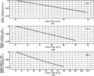
Fig. 8. Extent of variation from nominal capacity produced by voltage change
in ceramics of 3 different voltage ratings.
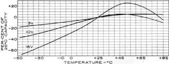
Fig. 9. Curves show capacitance change produced by temperature variation
in ceramics of three different voltage ratings.
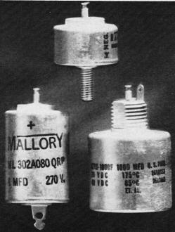
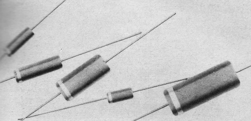
Fig. 10. Liquid-electrolyte, sintered-anode, tantalum capacitors by Mallory.
Unit at lower right is rated at 1000 μf.
Very refined aluminum must be used, otherwise small impurities of copper and
iron, when immersed in the electrolyte, form little batteries, which cause hot spots
and leakage currents that eat away the foil. This process is called "local action."
Shelf life is limited because of this factor and also because the aluminum oxide
tends to dissolve after a period of time.
Tantalum capacitors, which offer the highest microfarad-volt rating per cubic
inch to be found in any capacitor, offer a number of advantages over aluminum types.
Tantalum is more inert than aluminum, so it is possible to use much thinner sheets
without incurring a risk of puncture due to local action. Tantalum sheets 1/2-mil
thick are used, compared with 2- to 5-mil sheets of aluminum. This permits a great
size reduction in the case of tantalum capacitors. Furthermore, shelf life is extended
indefinitely.
Tantalum electrolytics are also made with sintered anodes (Fig. 10) instead
of the more conventional foil. Capacitors of this kind are constructed with a porous,
sintered slug which, when immersed in a suitable electrolyte, serves as the anode.
The porous material provides a very large area over which an oxide film is formed.
As a result, they are much smaller than foil types for equivalent voltage and capacitance
ratings. Units of this kind have been made which can be used at temperatures as
high as 200°C.
The sintering technique is not a new one to electronics, being used to form the
electrodes of some battery types and other components. It involves the application
of heat to form a powdery substance into a single mass, without actual melting.
The development of solid-dielectric tantalum capacitors represents a major advance.
These devices employ a solid-sintered tantalum slug that has been previously anodized.
The solid electrolyte is introduced into the pores of the slug, usually as a solution
of manganese nitrate or sulfate. It is then converted to manganese dioxide by heating.
Solid-dielectric tantalum capacitors have longer life expectancy and improved
electrical characteristics. The fact that no liquid is involved permits them to
be employed at temperatures as low as -80° C.
The element niobium has characteristics very similar to tantalum, and developmental
work is underway to produce niobium-foil electrolytic capacitors. A niobium capacitor
should have exactly the same capacitance as a tantalum capacitor of the same volume.
Although niobium has twice the dielectric constant, the anodic film which is grown
on it is twice as thick as that of tantalum, so the net result is a capacitor of
comparable rating.
As experimentation goes forward, however, this type may exhibit other characteristics,
now unrecognized, that will make it distinctively useful in certain applications.
If it does, it will merely serve to demonstrate further that there is still room
for refinement and improvement of a common component type that has been in use for
decades.
Connected to the input of transistorized equipment, this bridge permits the passage
of d.c. in the correct polarity only, regardless of connections to the battery.
Posted July 18, 2024
(updated from original post on 11/15/2016)
|