|
July 1965 Electronics World
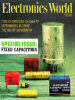 Table of Contents
Wax nostalgic about and learn from the history of early electronics. See articles
from
Electronics World, published May 1959
- December 1971. All copyrights hereby acknowledged.
|
A quick search for paper capacitors
turned up no manufacturers currently offering them. They were the capacitor of choice
for many decades until other types with superior dielectric material could be produced
at competitive prices. A special formulation of Kraft paper of various thicknesses
and chemical impregnations serves as the dielectric material between layers of conductive
foil. The vast majority of tubular type capacitors found in radios, televisions,
etc., prior to about 1960 were paper. One of the biggest disadvantages of paper
capacitors is vulnerability to drying out or absorbing moisture either through the
encapsulating material or via leaks in the case or around the external radial leads.
Most people who restore vintage electronics replace all paper capacitors out of
an abundance of caution, particularly because of the high voltages used by vacuum
tubes. Author William Robinson does a great job describing how paper capacitors
are manufactured, how they are used, and what their electrical characteristics are.
He tells the difference between a "wet" and a "dry" paper capacitor, which I've
probably known in the past, but had forgotten. This July 1965 issue of Electronics
World magazine presents similar articles on many types of capacitors.
Paper Capacitors

Fig. 1 - Capacitance change with temperature for kraft paper
dielectric material showing effects of various impregnants.
By William M. Robinson/ Chief Engineer, Cornell-Dubilier Electronics Div., Federal
Pacific Electric Co., New Bedford, Mass.
One of the most widely used types of capacitor, the paper type has characteristics
mostly dependent on the type of impregnant used.
Probably the least exotic member of the capacitor family is the paper-dielectric
capacitor. It is well known that mica types have much better over-all electrical
characteristics, film dielectrics have lower losses and better resistance to humidity,
and electrolytics and ceramics are smaller in size and lower in cost. Yet, after
seventy years of commercial application, paper capacitors are still the most widely
used capacitive component.
Paper capacitors range in physical size from the sub-miniature to huge complex
banks - in ratings from a few volts to hundreds of thousands of volts. Paper capacitors
are well suited for a.c. or d.c. service, pulse and energy-storage applications,
and for use in simple electronic devices or the most complex computers.
Basic Construction
Basic materials for all paper-capacitor elements are kraft paper, aluminum foil,
and a liquid wax or resin impregnant. The type of paper and impregnant, as well
as vital design factors, determine the rating and establish the over-all performance
characteristics of the finished capacitor. Packaging in a metal or insulated housing,
together with the type of terminals used, limits or extends the capacitor's capability
with respect to environmental performance.
Dielectric Structure

Fig. 2 - Insulation resistance characteristics of paper capacitors
showing effects of the various types of impregnants.
A paper capacitor receives its name from its basic dielectric material, kraft
paper. This material is not just a porous separator as found in electrolytic capacitors
but is a vital part of the dielectric structure.
Kraft capacitor tissue is manufactured from specially selected unbleached sulfate
pulp made from certain species of soft woods. These pulps are chosen for their uniformly
long fibers and high degree of purity. The pulps are made to rigid specifications
to insure that the fiber length, chemical composition, and purity of each lot will
meet exacting requirements.
There are many types and grades of kraft for use as a dielectric. Some of these
perform better on a.c., others on d.c., depending upon the dielectric strength and
dissipation factor.
Aluminum foil used for paper capacitors ranges from 0.00017 to 0.0005 inch in
thickness and has a purity of at least 99.8 %. The surfaces must be free from all
traces of rolling lubricants and other sources of contamination. Although tin-lead
alloy foil is occasionally used on very small capacitor elements, aluminum is preferred
because of its resistance to corrosion and electrochemical action, both of which
are apt to severely degrade the capacitor electrical characteristics under certain
operating conditions.
Use of impregnants for kraft paper improves the dielectric strength greatly and
increases the dielectric constant, consequently reducing both the size and cost
for any given capacitor rating. The impregnant also establishes the temperature-capacitance
characteristics as shown in Fig. 1 and is an important factor contributing to the
insulation resistance and dissipation factor of the finished capacitor. Some impregnants
are used exclusively in capacitors for d.c. service, others for a.c. capacitors,
depending upon the dissipation factor and dielectric strength they impart.
Design Factors
The voltage rating is established by the selection of the type, thickness, and
number of layers of kraft paper, together with the characteristics of the impregnant
used. Insulation spacing between metal parts of the element is directly related
to the voltage rating. Capacitance is proportional to the area of the aluminum-foil
electrodes and inversely proportional to the distance between the electrodes. Design
factors determining capacitance are C = (0.225 A K)/(T x 103) where A
is the active electrode area in square inches, K is the dielectric constant of material,
T is the dielectric thickness in mils, and C is the capacitance in microfarads.

Fig. 3 - How temperature affects life of a paper capacitor.
Winding of the capacitor element is accomplished with automatic or semi-automatic
machines to minimize hand contact and to assure uniformity of the product. Fig.
4A shows a wound roll of kraft and aluminum foil together with inserted tinned-copper
contact strips. The extended-foil type of winding, shown in Fig. 4B, has the foil
protruding so connections may be made externally. Inserted-tab construction is generally
used for d.c. or low-frequency a.c. capacitors, the extended foil being used for
the smaller sizes, those used at higher frequencies, or where high-current pulses
or discharges are required in operation.
Paper capacitors are usually made with two aluminum foils separated by two or
more layers of kraft. Higher voltage windings often employ twelve or more papers
with as many as six foils.
Many of the smaller, lower-cost paper capacitors for the entertainment field
are impregnated at this stage. Assembly in non-metallic molded, tubular, or dipped
enclosures follows the operation of attaching lead wires. This is the wet-assembly
method of manufacture.
Most military and industrial capacitors, including all those for a.c. and higher
voltage ratings, are made by the dry-assembly process. This consists of assembling
the windings in metal containers and, after seaming, conducting the impregnation
process through a small hole in the case. The hole is then sealed.
Dry-assembly processed capacitors are made in almost an infinite variety of shapes
and sizes using squeezed-seam, rolled-seam, and welded-seam containers.
Terminal connections and insulators range from the sub-miniature to extremely
large sizes. The capacitor element and internal circuit connections are generally
heavily insulated from the case with thick sheets of kraft paper made to the same
requirements as for the dielectric paper.
Impregnation
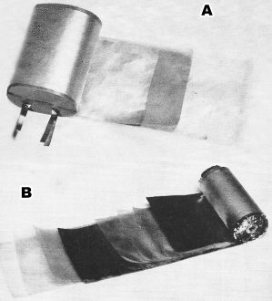
Fig. 4 - (A) Paper capacitor element made with inserted contact
tabs. (B) Paper capacitor element extended foil construction.

Fig. 5 - How voltage affects the life of a paper capacitor.
Capacitors are loaded into the impregnation tanks where they are subjected to
extended heat and vacuum cycles to remove all traces of moisture and air. This process
is conducted at temperatures well below the critical level. which would be harmful
to the kraft paper, by extending the time and monitoring the temperature and vacuum
frequently. Force-drying the elements at excessively high temperatures to reduce
process time is generally detrimental to reliable operation.
After the internal parts of the capacitor element have been thoroughly evacuated
and dried, the tanks are flooded with the impregnant. Alternate vacuum and pressure
cycles are applied so that every fiber of the paper is thoroughly impregnated and
all voids are removed.
Finishing and QC
At the end of the impregnation cycle, the capacitors are removed from the tanks,
drained, sealed, and cleaned, and markings are applied over plain, painted, or plated
finishes. The QC (quality-control) program includes 100% tests of capacitance, dielectric
strength, seal, and mechanical inspection, as well as statistical checks of insulation
resistance and dissipation factor.
Test facilities are used to conduct life tests to determine quality-level and
service-life capabilities to verify design standards and to accumulate data for
reliability studies.
These facilities consist essentially of high-temperature ovens with adjustable
a.c. or d.c. power supplies and controls to maintain specified test conditions.
Before any new design standard or material is used in a paper capacitor, it is thoroughly
evaluated under accelerated life conditions .
Special Constructions
The capacitors previously described are of conventional foil-paper construction.
Other types are made using series-wound elements with high-voltage ratings and low-inductance
conductors for energy-storage and pulse applications. Such capacitors often are
required to deliver discharges of tens of thousands of amperes in intervals as short
as a few microseconds.
Plastic films are also used in conjunction with paper for a dielectric having
special characteristics of capacitance change with temperature and an extremely
high insulation resistance. The mixed dielectric combines the best properties of
both materials, frequently resulting in a more reliable product, although at a higher
cost.
Metallized paper capacitors with vapor-deposited metal electrodes are available
where space will not accommodate standard capacitors. The smaller size is obtained
by use of electrodes less than one micron thick and reduced di-electric for a given
rating. This type of unit has limited self-healing properties upon voltage breakdown,
as the electrode material will fuse and clear by electrical discharge. Metallized
capacitors are used in ratings up to 600 v.d.c. They should not be employed in circuits
where high insulation resistance is a necessary critical requirement.
Power Losses
Even though paper capacitors normally perform to more than 99.5% efficiency,
there are internal power losses that must be considered for units operating in a.c.
or pulse circuits. The methods of calculating power loss for a.c. operation is Watts
Loss = D.F. (E2/Xc) where D.P. is the dissipation factor of
the capacitor, E is the applied r.m.s. sine-wave voltage, and Xc is the
capacitive reactance of the device involved.
The method of calculating power loss for pulse operation is Watts Loss = D.F.
(C E12 N) where C is the capacitance in farads, E1
is the applied peak voltage, D.P. is the dissipation factor of the capacitor, and
N is pulses per second.
Approximately 0.06 watt per square inch of case surface area will result in a
10°C rise above the ambient temperature, assuming the capacitor is operating in
still air. This temperature rise has a marked effect on capacitor life, as will
be described.
When making the calculations for power loss, the dissipation factor may be assumed
to range from 0.0025 to 0.005, depending upon the type of impregnant used. The actual
temperature rise may, of course, be measured by testing the capacitor under the
given conditions.
Effects of Temperature
Paper dielectric capacitors are designed to operate at ambient temperatures of
55°C, 70°C, 85°C, or 125°C, depending upon the design standards
and impregnants used. Chlorinated or mineral waxes and oils are generally imited
to 85°C. Silicone-fluid, certain resins, and polyisobutylene-impregnated capacitors
may be used to 125°C. Higher temperatures result in gradual decomposition of
the cellulose fibers of the paper, as well as chemical changes In the impregnants,
causing degradation of electrical characteristics of paper capacitors.
Effects of temperature and capacitance are shown in Fig. 1. The large loss in
capacitance for some impregnants is due to change in the dielectric constant of
these materials. Such capacitors recover full capacitance when returned to room
temperature. Units operating in a.c. or pulse circuits frequently generate sufficient
heat through internal losses to recover full capacitance after less than one hour
of operation, even though they are exposed to very low ambient temperatures.

Fig. 6 - Attenuation characteristics of conventional and feedthrough
capacitors as measured in a 50-ohm circuit.
Designers must also consider insulation-resistance changes with temperature.
Shunt leakages are often 100 times greater at high ambient temperatures than at
25°C. as shown in Fig. 2. Insulation resistance of capacitors may also decrease
with life due to the effects of moisture on units made in non-metallic cases and
chemical changes in those made in hermetically sealed construction. Circuits should
be designed to accommodate ten times the leakage current specified for a given capacitor
with an additional adequate allowance for operation at high temperatures.
Dissipation-factor changes with temperature are not significant except for capacitors
operating in a.c. or pulse circuits.
Life performance of paper capacitors is related to ambient temperature. A lO°C
increase may reduce life as much as 50%, as shown in Fig. 3. Use of capacitors at
temperatures below maximum rating is recommended to extend life and lower failure
rates. This may also be accomplished by using capacitors at less than rated voltage
where higher ambient temperatures cannot be avoided. When designing a mechanical
layout for equipment, capacitors should be located as far as possible, or thermally
insulated rom, sources of damaging heat such as tubes, transformers, and power dissipating
resistors.
Capacitor Precautions
1. Keep all large capacitors, high-voltage or high-capacitance types, fully discharged
with a low-resistance or shorting wire connected across the terminals. Many persons
have been seriously injured by touching capacitors long after they had been removed
from a source of voltage.
2. Install capacitors away from sources of heat such as tubes, transformers,
or power resistors.
3. Do not exceed the temperature or voltage ratings unless such service is approved
by the manufacturer.
4. Do not discharge a capacitor with a direct short circuit unless the capacitor
is rated for this type of service. Direct discharge may result in an exceedingly
high current flow from the capacitor or set up an oscillatory discharge which may
be harmful to the capacitor. Limit the discharge current to one ampere unless the
capacitor is designed for higher current service.
5. Keep non-metallic cased capacitors in a dry storage area, not exposed to a
humid atmosphere .
6. Solder connections to capacitors in a manner which will not damage the seal.
On wire-lead types, soldering should be done at least 1/4" away from capacitor body.
7. Use a torque wrench when tightening nuts to avoid damage to capacitor seal.
8. Do not subject capacitors to any unusual environmental conditions of vibration,
shock, pressure, or immersion without first checking with the manufacturer.
9. Allow a maximum of ventilation for a.c. or pulse capacitors operating at high
ambient conditions.
Voltage Effects
A well-designed paper capacitor generally is rated for a life capability of more
than 50,000 hours. However, service conditions may shorten or extend this time.
In addition to the temperature effects, the applied voltage also has a considerable
bearing on the successful performance of a capacitor.
Both industry and the military have accepted in their specifications the use
of the fifth-power rule relating to the voltage life of paper capacitors for d.c.
operation. The following equation shows the relationship between the applied voltage
and operating life: L2 = L1(V1/V2)5
where L1 is the life at rated voltage V1, L2 is
the life at voltage V2, V1 is the rated voltage, and V2
is the intended operating voltage.
Fig. 5 shows that operation for 20% under rated voltage will result in almost
a 300% increase in capacitor life. This factor applies mainly to hermetically sealed
paper capacitors, but it may also be applied to non-metallic cased types if desired
circuit operation is not critical with respect to the capacitor insulation resistance.
Frequency Effects
Electrical characteristics of capacitance and dissipation factor remain fairly
stable at increased frequencies. There may be a 5% to 10% loss of capacitance at
frequencies above 1 mc. as compared with 60-cycle or 100-cycle values. Dissipation
factors will also be somewhat higher.
Since all capacitors contain some degree of series inductance as well as shunt
resistance, the effect of these on impedance must be considered in circuit design.
Inductance is caused by circuit connections to the capacitor element. Series resistance
is also contributed by these connections and the foil electrodes. Shunt resistance
results from normal dielectric leakage.
At the higher frequencies, conventional paper capacitors can be expected to perform
as shown in Fig. 6 with exact characteristics dependent upon capacitance value and
type of circuit connections to the element. Feedthrough capacitors of coaxial construction
have much better frequency characteristics although they employ paper dielectrics.
When using d.c. paper capacitors in audio- or radio-frequency circuits, precautions
must be observed to limit voltage to prevent overheating and greatly reduced life.
At 60 cycles, the maximum voltage applied should be less than 20% of rating; at
1000 cycles, 6%; and at 10,000 cycles and higher, only 1%. These values may be exceeded
only if a specific capacitor is evaluated under the intended conditions of operation
and is found to stabilize within its maximum ambient temperature rating.
Posted September 8, 2022
|


