|
February 1967 Electronics World
 Table
of Contents
Table
of Contents
Wax nostalgic about and learn from the history of early electronics. See articles
from
Electronics World, published May 1959
- December 1971. All copyrights hereby acknowledged.
|
Operators didn't know how good
they had it in 1967. The story talks about the nuisance of having to sift through
"hundreds" of satellites, old rockets, and assorted space junk" in order to search
for and track potentially threatening objects in orbit around the Earth. We're into
the millions of objects in 2019, and the potential threats are infinitely larger.
The article mentions the use of an
AN/FPS-16 radar operating in C-band to detect and measure the returns and then
the results were analyzed in an attempt to determine the character of the object.
Open air test sites and anechoic chambers were used to measure the radar cross section
and characteristic signature of many shapes to populate a database of recognizable
returns that would help to determine whether the space object was friend or foe.
Radar Signature Analysis
By Edward A. Lacy
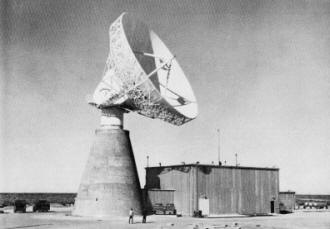
Typical of the radars used for signature analysis is this advanced
projects terminal measurements radar built by Raytheon for the White Sands Missile
Range in New Mexico.
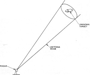
Fig. 1 - Since the radar beam is much wider than the target,
exact shape and size of target may be unresolved.
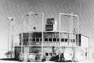
Over-all view of the control house at the Air Force radar target
scalier site (Rat Scat). The two antennas at the right are 10-ft dishes, while two
at the left are 6-ft dishes. These antennas are elevated on individual tracks when
they are being used for radar target measurements.
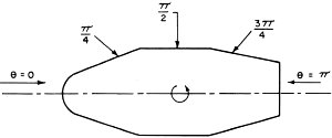
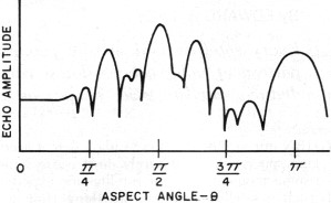
Fig. 2 - A compound body along with its radar signature.
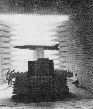
The target end of Bunker-Ramo Corp.'s microwave anechoic chamber.
Foam plastic pyramids lining chamber absorb radiation.
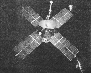
Satellites such as Mariner IV have a more complicated radar signature
on account of the solar-cell paddles that are used.
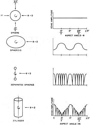
Fig. 3 - Typical patterns produced by symmetrical bodies.
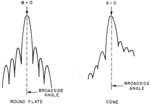
Fig. 4 - Patterns produced by rotating plate and cone.
Every satellite and missile produces a distinctive pattern of radar echoes. These
can be employed to deduce satellite size, shape, as well as motion.
When our satellite-tracking radars detect a new foreign space vehicle, it surely
must cause some worrisome moments for our intelligence experts. For, after all,
such a satellite could be anything from a harmless scientific experiment to a surveillance
vehicle or, worse yet, a satellite equipped with a nuclear or biological warhead.
With hundreds of satellites, old rockets, and assorted space junk now in orbit
and with many of them passing over the continental United States, it has become
important to our military peace of mind to know the origin, capabilities, and intentions
of each of these objects. To determine this, the Air Force is building a surveillance
system to detect, track, identify, and catalogue all objects in space on their first
orbit.
Lest this sound like a simple matter, it should be noted that until recent years
it just was not possible for us to determine much, if anything, about such objects.
Of course, our radars told us the altitude, range, and velocity of a given satellite,
but even with the most precise radars it was not possible to "paint" a picture of
the satellite, that is, resolve the target in angle. As shown in Fig. 1, a radar's
beam is ordinarily too wide to give any indication of the shape of a satellite which
is an important factor in determining its mission or intent. At a distance of 100
nautical miles from the antenna, for instance, a radar beam may be a mile or more
wide. To use such a beam to paint a silhouette of an object only a few feet in diameter
is like trying to fill in a "paint by number" drawing with a 6-inch brush.
While much of this information is still "classified" by the military, enough
has been released to indicate how a new technique, called "signature analysis" -
a remarkable bit of engineering detective work, is being used to determine satellite
size, shape, and motion.
Radar "Fingerprints"
Although the new system hasn't been refined to that extent as yet, it is almost
as if each satellite or reentry body has its own radar "fingerprint", which is a
plot of the signal strength of the radar echo (as recorded in the automatic gain
control circuit) versus time. In this technique, plots or signatures of the target
echo are broken down into patterns that represent the returns from objects of known
shape. These shapes are then put back together to define the complete shape of the
satellite - whether it is a cone, cylinder, sphere, or some combination of these
shapes (Fig. 2). Using other techniques of signature analysis, it is then possible
to determine the size of the satellite, its orientation if it is not tumbling, and
its tumble rate if it is tumbling.
Knowing these characteristics of the satellite, the analyst may then be able
to determine the satellite's intended mission. For example, if the satellite is
always oriented toward the earth as it passes over us, then it could very possibly
be a surveillance satellite. Particular shapes are optimum for certain types of
sensors used on surveillance satellites. On the other hand, extreme altitudes would
indicate that the satellite probably is not spying on us. By using this information
and making deductions, we can obtain a pretty good description of the craft.
Although plots of aircraft radar echoes have been available for several years,
it should be noted that signature analysis really began only in 1958. In that year
D. Barton of RCA was able to deduce the contours of Sputnik 2 from the plots of
echoes received on an AN/FPS-16 radar. By this process it was shown that complex
patterns of radar returns could be resolved into combinations of returns representing
simpler shapes and then put back together to indicate the original shape. In the
RCA publication, "An Introduction to Target Recognition", from which much of the
information in this article was derived, Charles Brindley reveals many of the techniques
used in signature analysis.
Cross-section Measurements
Signature analysis is based on radar cross-section: predicting it, measuring
it, recording it, and recognizing it. Radar cross-section is simply the size of
an object as it appears to a radar, irrespective of its actual size. While there
is no simple relationship between radar cross-section and actual size, generally
the larger the object, the greater its radar cross-section or reflectivity.
Obviously, the greater an object's cross-section, the easier it will be for the
radar to see it. Conversely, the smaller the cross-section, the harder it is for
the radar to acquire. The enemy takes advantage of this by shaping reentry bodies
so as to reduce their radar cross-section and by coating the vehicles with a radar-absorbing
material. Radar cross-section depends on radar frequency, the angle at which the
beam strikes the target, and the polarization of the signal.
To obtain laboratory cross-section data of actual satellites and other objects
is a difficult matter: it is hard to maneuver the satellite into known aspects,
satellites are expensive, and it is hard to repeat measurements. These difficulties
have lead to the development of test ranges, both indoors and out, for plotting
the cross-sections of various objects at rest.
In the indoor test range, called radar or microwave anechoic chambers, scale
models of various shapes and sizes are observed with radars which are scaled down
in size and up in frequency. Special radar absorbing materials are placed on the
walls of the chamber to prevent unwanted reflections. The scale-model test object
is placed on a turntable so that various aspect (viewing) angles may be obtained.
The radar signal is bounced off the object and the signal strength of the echo is
recorded on a strip-chart.
Anechoic chambers have the advantage of being immune to bad weather: you can
use them when it is raining, something you can't do with outdoor ranges since the
rain absorbs too much of the signal at the frequencies used on the model ranges.
Such chambers, though, can be an expensive proposition when waveguides and models
are built to small scale.
With outdoor test ranges the models do not have to be nearly as small. Avco has
a test range where 2500-pound models can be suspended up to 300 feet in the air.
At the radar target scatter site (called "Rat Scat") near Holloman Air Force Base,
New Mexico, static cross-section measurements can be made on objects weighing up
to 8000 pounds at frequencies from 100 to 12,000 MHz. On outdoor ranges such as
these, special care must be taken to eliminate or discount the return from the tower
or other supporting structures on which the target is placed since the tower may
have a greater cross-section than the target.
Various Types of Signatures
Now let us consider the various types of signatures or returns which we obtain
for bodies of various shapes, based on test range measurements. Figs. 3 and 4 show
the returns for a sphere, cone, cylinder, and other shapes. The returns shown are
for rotating bodies at a fixed position: the lobes may vary in width and number
for moving bodies.
Since a sphere looks like a sphere no matter how you view it, its radar cross-section
will be a constant level with no variation because of different aspect angles. The
cone and cylinder have more complicated returns because the strength of the echo
will depend on the angle or aspect at which the beam strikes the object. By the
use of certain approximations, most symmetrical bodies can be considered to be made
up of combinations of these basic shapes. If the satellite is not symmetrical (for
example, if it has solar cells mounted on paddles), the analysis problem becomes
more difficult.
In either a test range radar or an operational radar, the target signature may
be obtained from the automatic gain control circuit or the video circuits of the
radar receiver. The recording of the a.g.c. voltage versus time is usually made
with an analog strip-chart recorder. While this technique gives a good indication
of the average strength of the return signal, it is being replaced at many stations
by a video tape recorder which furnishes much more information since it records
on a pulse-by-pulse basis.
Using the recording of an operational radar and knowing the characteristic returns
of certain bodies obtained with a test range radar, the signature analyst can be
expected to come up with a reasonable approximation of the unknown body, provided
that both radars were looking at the target at the same angle.
Now that we've established the shape of the satellite, let's consider its motion.
While the more sophisticated satellites will be stabilized, it is possible for the
satellite to be tumbling which would indicate either a failure of the satellite
to perform as programmed or a lack of engineering ability on the part of the designers
and builders. In either case, it is important to know if the satellite is tumbling
and, if it is, the tumble rate. This can be determined by observing periodic repetitions
of the same cross-section pattern.
Thus far we have considered the cross-section just as a pattern and have ignored
units of measurement. To use cross-section to determine actual size of a satellite,
it is necessary to calibrate the radar, One method that has been used is to track
a 6-inch sphere suspended below a balloon and then calibrate the relationship of
the radar cross-section and the radar return accordingly.
By using appropriate formulas and by counting the number of lobes in one period,
one can find the length and radius of the object.
Reentry Body Study
Besides satellite target recognition, signature analysis is being used to study
reentry bodies. When a reentry vehicle enters the atmosphere, the shock waves formed
by the vehicle cause a plasma sheath - a concentrated layer of electrons-to be formed
on the vehicle. The plasma sheath has a drastic effect on the cross-section - the
reentry vehicle may show a significant increase or decrease in cross-section compared
to its cross-section as measured in free space. The ionized field - called the "wake"
- which trails behind the vehicle will show similar effects. Using signature analysis,
we can then determine how the vehicle is being affected by reentry.
In the military area, anti-radar signature devices (decoys) use built-in electronics
to reshape the returning radar echoes so that a small, inexpensive decoy can "look"
like a larger reentering vehicle.
A more important use of signature analysis is to be able to determine which reentry
bodies are enemy war-heads and which are merely decoys in the mass of reentry bodies.
Since the warhead must be identified in time for us to take defensive action, a
computer is necessary. A computer, however, tends to take things too literally:
if a return differs only slightly from the description which was given to it, the
computer will not recognize the object. But with new computers which are capable
of learning and with improved optical techniques for pattern recognition, perhaps
this problem is closer to solution.
Posted April 17, 2019
(updated from original post on 1/30/2012)