|
May 1967 Electronics World
 Table
of Contents
Table
of Contents
Wax nostalgic about and learn from the history of early electronics. See articles
from
Electronics World, published May 1959
- December 1971. All copyrights hereby acknowledged.
|
Some things never change, and
the basic definition of a pulse waveform is one of them. This article form the May
1967 edition of Electronics World magazine does a nice job of defining
the fundamental characteristics of a pulse, including rise and fall times, overshoot,
pulse width, etc. Ham shacks and company labs alike are still stocked with the venerable
HP 215A and
HP 213B signal generators that appear in this piece. If you're lucky, you can get a good
deal on them from someone on eBay.
Selecting and Using Pulse Generators
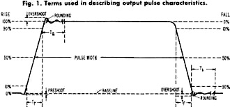
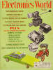
Fig. 1 - Terms used in describing output pulse characteristics.
By John LenkBasically a laboratory version of the square-wave generator, but
with adjustable on-off times, this instrument has many uses in developing digital
circuitry, in checking diode and transistor switching times, as a klystron modulator,
and for impulse testing.
The output of a pulse generator is similar to that of a square-wave generator.
The fundamental difference between the two concerns the signal duty cycle. Square-wave
generators have equal "on" and "off" periods, equality being retained as the repetition
frequency is varied. On the other hand, the duration of a pulse generator "on" period
is independent of pulse repetition rate. The duty cycle of a pulse generator can
be made quite low that the pulse generator is usually able to supply more power
during the "on" period than a conventional square-wave generator.
Pulse generators with fast rise times are widely used in the development of digital
circuitry. Teamed with suitably fast oscilloscope, these generators enable evaluation
of transistor and diode switching times. Pulse generators can be employed as modulation
sources for klystrons and other r.f. sources to obtain high peak power while maintaining
low average power. Pulse generators are also used for impulse testing. A very short
pulse is rich in harmonics so that input testing amounts to simultaneous frequency-response
testing of components or systems.
Important Characteristics
Hewlett-Packard 215A pulse generator is shown.

HP-213B produces pulse with under 0.1-nanosecond rise time.
To adequately describe the characteristics of a pulse generator, it is first
necessary to establish uniform terms for pulses. These terms are illustrated in
Fig. 1. When actual pulses are very irregular (with excessive tilt, over-shoot,
or rounding), the definitions may become ambiguous, requiring a more complete description.
The following are typical characteristics of a laboratory pulse-generator output:
Leading Edge Only:
Rise time (Tr): <1.0 nanosecond (ns) (10 to 90%).
Overshoot and ringing: overshoot <5% peak; ringing <±5% of pulse amplitude.
Corner rounding: occurs no sooner than 95% of pulse amplitude.
Time to achieve flat top (Ta): <6 ns.
Trailing Edge Only:
Fall time (Tf): <1.0 ns (10 to 90%).
Overshoot: <5%.
Rounding: occurs no sooner than 95% of fall.
Time to settle within 2% of baseline (Tb): 10 to 25 ns, varies with
setting.
Baseline shift: < 01 % under all conditions.
Preshoot: <1%.
Perturbations on flat top: <2% of pulse amplitude.
Peak voltage: >10 volts into 50 ohms, >20 volts into open circuit.
Polarity: positive or negative.
Pulse width (between 50% points): continuously adjustable, zero to 100 ns (zero
ns width occurs when 50% points meet, creating an impulse of one-half the amplitude
of wide pulses).
Repetition rate (internal): <100 Hz to >1 MHz in 4 ranges.
The quality of the output pulse is of primary importance in the selection of
a pulse generator. If the displayed pulse is degraded, a high-quality test pulse
will insure that the cause is in the test circuit alone. Rise and fall times should
be significantly faster than the circuits or systems to be measured. Any overshoot,
ringing, or sag in the test pulse should be known so that these faults will not
be confused with similar results caused by the test circuit.
The range of pulse-width control should be wide enough to fully explore the range
of operation of a circuit. Narrow pulse widths are useful in determining the minimum
trigger energy required in some circuits.
Maximum pulse amplitude is of prime concern if appreciable input power is required
by the circuit under test, such as a magnetic core memory. At the same time, the
attenuation range should be broad enough to prevent over-driving the test circuits
as well as to simulate actual circuit operating conditions.
The range of pulse repetition rates is important if the tested circuits can operate
only within a certain range of pulse rates or if a variation in the rate is needed.
In some systems, methods of external triggering are also significant. In fast pulse
systems, the generator source impedance is an important consideration because a
generator which has a source impedance that is matched to the connecting cable will
absorb reflections resulting from impedance mismatches in the external system that
is used.
Basic Precautions
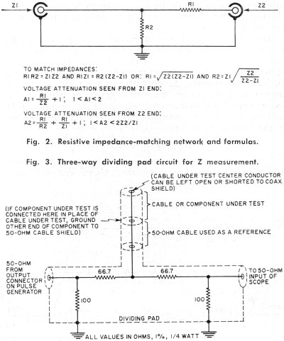
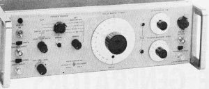
Fig. 2 - Resistive impedance-matching network and formulas.
(upper)
Fig. 3 - Three-way dividing pad circuit for Z measurement. (lower)
1. Use proper types of cables, terminations, attenuators, and impedance-matching
networks. Always match impedances unless the test circuit specifically calls for
a mismatch.
2. Keep ground-return paths short and direct. Use heavy conductors to provide
low impedance in the ground return.
3. Make sure that all connections are tight and that all connectors are securely
assembled.
4. Shield measuring-equipment leads to prevent undesired coupling to other parts
of the circuit. Shielding is especially required where pulse radiation is a problem
and particularly where high-impedance dividers or circuits are involved.
5. Consider the effects of secondary parameters in components, such as inductance
in resistors and in capacitor loads.
6. Consider the possible non-linear behavior of components due to changes in
either voltage or temperature.
7. Select components which function properly at the frequencies and rise times
expected to be encountered.
Obviously, the accuracy of rise-time measurements can be no greater than the
rise time of the pulse generator. If a pulse generator with a 20-nanosecond rise
time is used to measure the rise time of a 15-nanosecond oscilloscope, the measurements
would be hopelessly incorrect. Also, if the same pulse generator and oscilloscope
were used to measure the rise time of another system, the fastest rise time for
accurate measurement would be something greater than 20 nanoseconds.
As a general rule, if the rise time of the test device is at least ten times
as long as the rise times of the generator, oscilloscope, or cables, the error introduced
will not be more than 1%. If the rise time of the device under test is less than
ten times that of the test equipment, it will be necessary to calculate the rise
time. The most common method involves finding the square of all rise times associated
with the test, adding these squares together, and then computing the square root
of this sum. For example, using the 20-ns pulse generator and the 15-ns oscilloscope,
the calculation would be: 20 x 20 = 400; 15 x 15 = 225; 400 + 225 = 625. √625 =
25, so 25 nanoseconds is the fastest possible rise time capable of measurement.
Another rule of thumb applying to rise times is that if the equipment being measured
has a rise time three times slower than the test equipment, the error is only slightly
less than 6%.
If there are significantly long lengths of coaxial cable in the signal path,
the above method can be used only as an approximation, since the "skin-effect" losses
in coaxial cables do not add properly with this method.
Connecting Pulse Generators
1. In most measurements involving pulse generators, a complete d.c. return path
must be provided between the device under test and the pulse-generator output connector.
2. If the pulse is applied to a load which has a d.c. potential across it, the
actual amplitude of the pulse is equal to the voltage set by the pulse-generator
amplitude control less one-half the d.c. voltage across the load.
For example, assume that the pulse-generator output is connected to a load which
has +10 volts across it and that the pulse-generator amplitude control is set to
+1 volt. The actual amplitude is found by substituting these values as follows:
Va = Vs - (Vl/2) or +1 - (+10/2) = -4 volts where
Va is the actual pulse amplitude, Vs is the voltage setting
of the amplitude control, and Vl is the d.c. voltage applied across the
load.
3. If it is impossible to use an impedance-matching network, one possible solution
is to employ a long coaxial cable between generator and load. This will delay the
load's reflections until after the time of interest.
The pulse-generator output can be supplied with an impedance-matching network
that will produce a smooth transition of power (no reflections) with a minimum attenuation.
Such a network is shown in Fig. 2. To match impedances with the illustrated
network, the values of R1 and R2 must be selected carefully.
For example, to match a 50-ohm system to a 125-ohm system, Z1 = 50 ohms and Z2
= 125 ohms. Therefore, R1 = √125(125 - 50) = 96.8 ohms, and R2 = 50 √25/(125 - 50)
= 64.6 ohms.
The attenuation as seen from one end of the network does not equal that seen
from the other end. Using the equations shown in Fig. 2, it will be noted that
a signal applied from the lower impedance source Z1 encounters a voltage attenuation
A1. Also, a signal applied from the higher impedance source Z2 will encounter a
greater voltage attenuation A2.
For example, with an R1 of 96.8 ohms and an impedance Z2 of 125 ohms, A1 = (96.8/125)
+ 1 = 1.77.
With an R1 of 96.8 ohms, an R2. of 64.6 ohms. and an impedance Z1 of 50 ohms,
A2 = (96.8/64.6) + (96.8/50) + 1 = 4.44.
Measuring Impedance

Fig. 4 - Waveform obtained with 125-ohm cable and 50-ohm
system. (upper)
Fig. 5 - Test connections using generator with conventional
scope. (lower)
A pulse generator can he used to determine impedance of an unknown device by
comparing the reflected pulse with the incident pulse on an oscilloscope. This can
be explained as follows.
As a signal travels down a transmission line, each time it encounters a mismatch
or different impedance, a reflection is generated and sent back along the line to
the source. The amplitude and polarity of the reflection arc determined by the value
of the impedance encountered in relation to the characteristic impedance of the
cable. If the mismatch impedance is higher than that of the line, the reflection
will be of the same polarity as the applied signal; if it is lower than that of
the line, the reflection will be of opposite polarity.
The reflected signal is added to or subtracted from the amplitude of the pulse
if it returns to the source before the pulse has ended. Thus, for a cable with an
open end (no termination), the impedance is infinite and the pulse amplitude would
be doubled. For a cable with a shorted end, the impedance is zero and the pulse
would be canceled.
The following procedure provides a practical method of determining impedance
with a pulse generator and scope.
1. Connect the equipment as shown in Fig. 3.
2.Observe the incident and reflected pulses on the oscilloscope. Using Fig. 4
as a guide, determine the values of V0 (incident) and Vx (reflected).
(This method is generally limited to the first reflections unless the deviations
are small, due to multiple reflections and reflection losses.)
4. Using the following equation, calculate the unknown impedance. Z = 50/(2V0/Vx
- 1) where Z is the unknown impedance, V0 is the peak amplitude produced
by the 50- ohm reference impedance, and Vx is the peak amplitude at the
time of reflection.
Using Conventional Oscilloscopes
A pulse generator is often used with a sampling oscilloscope, and generator and
oscilloscope manuals describe the procedure. However, a pulse generator can also
be used with conventional triggered oscilloscopes. Fig. 5 shows the test connections.
Internal triggering is convenient since no external triggering connections are
required. However, with external triggering it is possible to observe the shaping
and amplification of a signal pulse in the circuits of a device under test without
resetting the oscilloscope triggering controls for each observation. If the external
triggering signal is derived from the waveform at the input circuit of the device
under test, the time relationship and phase between the output and input waveforms
may be seen and compared on the oscilloscope screen.
If the signal from the test device is fast-rise non-repetitive or has a low duty
cycle, the oscilloscope used in this setup must have an internal delay line so that
the leading edge of the single waveform can be readily observed on the scope.
One of the drawbacks to a conventional oscilloscope is that the frequency response
of the test device may fall outside the bandwidth limitations of the vertical amplifier
system of the oscilloscope. In some cases, the output signal from a device under
test can be observed by direct connection through coupling capacitors to the vertical
deflection plates of a conventional oscilloscope. Thus, the limited bandwidth of
the oscilloscope vertical amplifier can be bypassed.
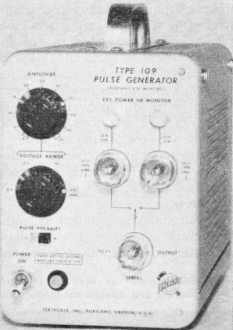
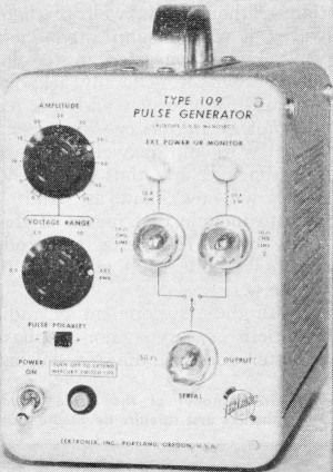
Tektronix Type 109 pulse generator has rise time of under 0.25
nanoseconds.
The following factors pertaining to the vertical deflection-plate system must
be considered for pulse measurement: d.c. operating potential of the plates, lead
inductance, deflection-plate capacitance, transit-time limitations, delay lines,
and deflection factor.
A typical circuit for direct a.c. coupling to the vertical plates is shown in
Fig. 6. This circuit permits the internal vertical amplifier of the oscilloscope
to be bypassed but still allows the normal d.c. operating and positioning voltages
to be applied to the deflection plates from the internal vertical amplifier. However,
when using this circuit, a high-quality external delay line must be used. This will
retard the pulse sufficiently to get it on the scope screen.
The values of R1 and R2 are found by solving the equation given in Fig. 6.
The resonant frequency (F0) of the leads and the capacitance of the deflection
plates (CD) for use in the equation may be determined by the following
procedure:
1. Turn off the oscilloscope power.
2.Disconnect the vertical amplifier leads from the CRT neck pins. (A convenient
method of connecting to the deflection-plate pins is to use clips removed from a
miniature tube socket.)
3. Cut a wire loop equal in length to the total length of C1, C2, R1, R2, R3,
and R4.
4. Temporarily substitute the wire loop for the components between the vertical
deflection-plate pins.
5. Bring a grid-dip meter near the loop and measure the resonant frequency (F0)
6. Remove the wire loop.
7. With a capacitance meter, measure the total capacitance between the plates
(CD) at the deflection-plate neck pins. (Capacitance between the plates
can also be found by referring to the specifications of the oscilloscope.)
Since the deflection plates are located close to the path of the electro beam,
a small amount of current will flow in the deflection-plate circuits The values
of R3 and R4 must be low enough so that this current will not produce a large voltage
drop at the deflection plates. If the resistors are too large, distortion, defocusing,
or positioning difficulties may be experienced. Since the deflection-plate current
varies non-linearly with the position of the beam, the effects are most noticeable
when the beam is positioned near the top or bottom of the screen. The approximate
value of 100,000 ohms that is given for R3 and R4 will probably be satisfactory
in most cases.
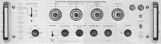
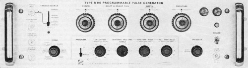
Tektronix Type R116 pulse generator.
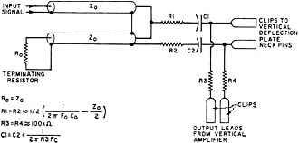
Fig. 6 - Circuit for coupling to vertical deflection plates.
C1 and C2 should be physically small to minimize lead inductance. The values
of C1 and C2 are selected on the basis of the required low-frequency response and
may be calculated from the equation given in Fig. 6. (Fc is the
low-frequency cut-off.) For example, if R3 and R4 are 100,000 ohms and if the desired
Fc is about 1.6 kHz. C1 and C2 should be 0.001 µF.
The stub cable that connects to terminating resistor R0 should be
long enough so that if a double-transit reflection appears, it can be easily identified
and corrected by adjustment of the termination.
For making vertical measurements with the test setup, the deflection factor of
the oscilloscope must be known. This can be measured as follows:
1. While the leads from the vertical amplifier are connected to the deflection-plate
neck pins, connect a d.c. voltmeter between the pins.
2. Measure the voltage change as the beam is positioned vertically over the full
height of the graticule.
3. Divide this voltage excursion by the graticule height in divisions to obtain
the deflection factor in volts/division.
(Many of the diagrams and techniques described above are based on information
from Tektronix, Inc. and Hewlett-Packard. -Editor)
Posted March 17, 2022
(updated from original post on 3/28/2012)
|