Silicon Controlled Rectifiers - New Applications in the Home |
|
Silicon controlled rectifiers (SCR) have been around for half a century and are still workhorses in power control and switching circuits. The SCR's usefulness comes both from being a diode with a settable forward conduction point ('breakover voltage') and its property of continuing to conduct below that threshold voltage once it has been reached. It then stays 'on,' acting like a conventional bipolar junction diode until p-n junction is no longer forward biased. At that point the diode is 'off' again until the breakover voltage is once again reached. When a sinewave is applied, as in a power supply design, this action allows the SCR to be turned on for less than half a cycle as a standard diode would do. Yes, you could design a biasing circuit to prevent a standard diode from conduction until a voltage is reached that is higher than the p-n junction barrier voltage, but then it would also turn off once the applied voltage dropped back below that level, whereas an SCR keeps conducting all the way down to the p-n junction barrier voltage. Figure 6 in the article illustrates the behavior. See Lothar Stern's article titled "Some 'Technical Terms' Aren't," in the June 1969 issue of Electronics World. Silicon Controlled Rectifiers - New Applications in the Home By Lothar Stern Motorola Semiconductor Products Inc.
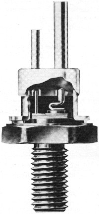
Already used in industry for power-control applications, recent drastic price cuts make the SCR attractive for use in electrical appliances and lighting circuits for the home. Editor's Note: The operating principles of SCR's, as described here, are the same whether these semiconductor devices are used to control large amounts of current in an industrial application or smaller current in a home appliance. Because of recent price reductions, the technician can expect to see more of these devices, not only in industrial plants, but also in high-volume-produced electrical appliances for home use. Although some of the highest current SCR's used in industry may cost several hundred dollars each, the 18-amp. units discussed below are priced as low as $1.80, in quantities of 5000. All too often there is a substantial lag between the development of a new device and its actual commercial use in applications for which it is obviously well suited. Such has been the case with transistors in television applications where, until recently, the cost of a TV transistor complement has been considered too high in comparison with vacuum tubes to offset the apparent advantages of transistorization. It has also been the case with the silicon controlled rectifier (SCR) which has found widespread use for power-control applications in industrial equipment, but whose cost has been too high for the consumer mass market despite the operating improvements and flexibility it offers for both large and small home appliances. Now that SCR prices have been suddenly and drastically reduced, at least for original equipment manufacturing purposes, there has been a dramatic increase in interest in such devices for the electrical appliance market. By the end of the year, a number of manufacturers are expected to introduce SCR-controlled appliances in what may well prove to be a new and major breakthrough of electronic applications in the home. Basically an SCR is a four-layer n-p-n-p device (Fig. 1) whose primary application is in electronic switching and power-control circuits.
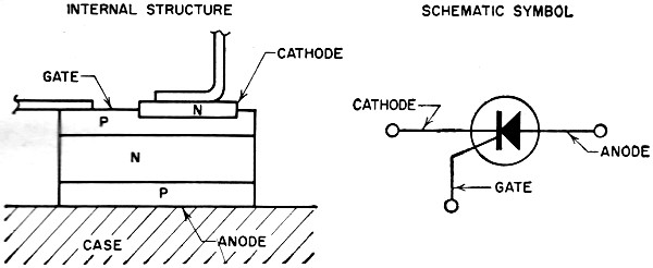
Fig. 1 - Simplified cross-sectional drawing showing the internal structure of the all-diffused silicon controlled rectifier. As a rectifier the SCR will conduct current in only one direction. But, unlike a conventional rectifier, which begins to conduct almost the instant its anode becomes even slightly positive with respect to its cathode, the SCR will remain nonconductive, even in a forward direction, until the anode voltage exceeds a certain minimum value called the "forward breakover voltage" (VBO) . Moreover, the value of VBO can be varied through the injection of a signal to the third or gate element of the device which governs the amplitude of the anode voltage needed to cause conduction or firing. It is this characteristic which makes the SCR an ideal switch or power-control device, especially in high-power circuits. In electronic switching, the SCR can successfully replace thyratrons, vacuum tubes, and power transistors. In electromechanical equipment, it replaces switches, relays, variable autotransformers, rheostats, and timers. As safety devices they can take the place of fuses and circuit breakers. Moreover, they can duplicate the functions of magnetic amplifiers and saturable reactors and can serve as high-speed protective devices and as lightweight, compact power controls. It is in the area of power control that they are likely to make their greatest impact on the appliance market. With SCR control it is possible to continuously vary the amount of current supplied to an electrical appliance, thereby providing a precise degree of control over the output of light and heat and over the speed of universal motors. While it may appear that similar control can be provided by a conventional rheostat, the SCR can accomplish this without the power wasting effect of rheostats and, in higher power devices, it can be less expensive and is much smaller and lighter than an equivalent rheostat would be in a similar application. How It Works For an over-all indication of how an SCR operates, consider the voltage-current relationship of the device as illustrated in Fig. 2. In this diagram, the gate terminal is considered to be open-circuited, or shorted to the cathode, and external voltage is applied only to the anode-cathode terminals. Under these conditions, it is evident that the reverse-bias voltage-current relationship (anode negative with respect to cathode) is identical to that of a reverse-biased conventional rectifier. As the reverse voltage is increased beyond the breakdown level, the semiconductor junction goes into avalanche and is usually destroyed because of the excessive junction temperature created by the relatively high power dissipation (voltage-current product).
Fig. 2 - Curve showing the anode-cathode characteristics of controlled rectifier with gate open or shorted to cathode. Under forward-bias conditions, however, the characteristics curve is entirely different. As forward bias is increased, in the region from A to B, there is virtually no current flow through the device (except for a small leakage current similar to the reverse leakage current). At point B, the forward breakover voltage, an avalanche action takes place and current tends to rise very rapidly. But, if the external load resistance is low enough to permit a rise in current to point C, an unusual "switchback" effect takes place. At the breakover-current value, point C, the voltage across the rectifier suddenly drops to a very low value, and the device acts very much like a conventional rectifier. The internal resistance of the device becomes very low and the current is limited primarily by the applied voltage and the external load resistor. Note here the difference between the reverse and forward characteristics of the SCR. In the reverse direction, when the avalanche breakdown voltage (X) is exceeded, the reverse current rises rapidly but the voltage across the device itself remains essentially at the breakdown value. The power dissipated in the rectifier, therefore, is extremely high and the device is usually damaged irreparably. For this reason, a rectifier or SCR is never operated beyond its reverse-breakdown point. In the forward direction, due to the switchback phenomenon, the internal resistance of the SCR suddenly switches from a very high to a very low value. Thus, in a circuit containing an SCR in series with a load resistor, the voltage across the SCR in a conductive state is negligibly small and current through the device can reach extremely high levels before rated junction temperature is exceeded. From the foregoing discussion it can be appreciated that the SCR, with the gate open or shorted, acts very much like a voltage-operated switch (provided the operating voltage is in the forward direction). At voltage levels below the breakover point, the switch is open, and beyond the breakover point the switch is closed. To cause a change in the switch position from "off" to "on," it is merely necessary to increase the source voltage, say, from zero to the breakover-voltage value. To cause a change in the switch position from "on" to "off," however, is quite another matter. In the "on" condition, the voltage drop across the SCR is extremely low and almost the total applied voltage appears across the external load resistor. Reducing the applied voltage does not materially change the voltage drop across the SCR. It does, however, reduce the current through the load resistance and, equally, through the series-connected SCR. Hence, as the voltage is reduced, current in the circuit decreases until a value is reached which is not sufficient to sustain the avalanche condition within the SCR. Below this current value, called "holding current," the SCR again reverts to its high-resistance condition and the switch is shut off. Using the Gate Terminal At this point one might logically ask, "What is the value of this type of performance?" It must be admitted that applications for this characteristic are indeed limited. There are some possible uses, as voltage-operated safety devices, for example, but the SCR's function for even these uses can be greatly improved by using its third or gate terminal. Consider now the theoretical static characteristics of the SCR which are often used to explain its operation with various current levels injected into the gate terminal, as shown in Fig. 3. With no gate current applied, the anode voltage must reach point A before breakover occurs. Now, if a small amount of voltage is applied to the gate so that the gate terminal is positive with respect to the cathode, gate current flows and the forward breakover voltage of the rectifier anode is reduced to point B. If the gate current is increased further, anode breakover occurs at point C and, for still higher levels of gate currents, the SCR characteristics approach those of a conventional rectifier, point D.
Fig. 3 - Static characteristics with various gate currents. The word "theoretical" has been emphasized in the above paragraph because this type of explanation can lead to erroneous assumptions regarding actual applications for the devices. It leads to the assumption, for example, that the SCR could be held at just below the breakover point for a certain anode potential by the application of a specified value of d.c. gate current. In actual practice, however, this is not the case. While the phenomenon of Fig. 3 can be readily observed, the gate-current range over which anode breakover is reduced from its open-gate value to virtually zero is extremely small. Moreover, this gate-current range varies from one device to another so that no accurate specifications of this type can be developed. Therefore, the conventional method of operating SCR's is to supply a gate signal of sufficient amplitude to assure firing of all devices. A plot as illustrated in Fig. 4 for Type MCR-808 devices, clearly shows the magnitude of gate voltage and current needed for reliable triggering. For these units it is seen that a gate signal of 3.5 volts and 0.1 ampere will trigger all devices of this type, although triggering for most devices can be achieved with much lower gate signal values.
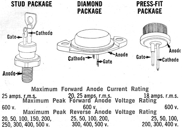
Fig. 4 - Gate firing characteristics of type MCR-808 SCR's. An important point here is that the amount of gate current required to change the VBO point from its zero-gate-current value to almost zero is very small - on the order of milliamps. And, since the SCR in the breakover or "on" condition can handle many amperes of current, the current gain of the device is quite high. In this respect the device acts very much like a sensitive relay where a small amount of current through the relay coil can control a much larger current in the relay contact circuit. There is, however, a major and important difference between the operation of a relay and an SCR. With a relay, the contacts will close as soon as an activating current is applied to the relay coil and they will remain closed only as long as the activating coil current is present. With an SCR, the "contacts" will close (the resistance between cathode and anode is reduced to a very low value) as soon as the required gate current is applied, but they will remain closed (the SCR will remain in a breakover condition) even if the gate current is removed. Once fired, the gate loses all control and the "switch" will remain in a "closed" or latched state irrespective of any current or voltage applied to the gate terminal. The only way to turn off an SCR that is in the "on" state is to reduce the anode current below the level of the holing current needed to sustain anode conduction. This, in a d.c. circuit, can be accomplished in a number of ways, such as mechanically interrupting the load current, reversing the voltage polarity from anode to cathode, shunting the major portion of the load current around the SCR, or by means of commutating capacitors or the use of LC circuits in the load circuit. For a.c. circuits, which are of primary interest in the home appliance field, the SCR is turned off at the end of each positive-going half-cycle of applied anode voltage. Ratings & Packages Today's SCR's are available with maximum forward-cur4ent ratings ranging from approximately 1 amp up to as much as 300 amps and with reverse breakdown voltage ratings from 25 to 1500 volts. Forward breakover voltages are normally much higher than reverse breakdown ratings so that a device that will break down under relatively low reverse voltages may be able to successfully block forward voltages of several hundred volts. Since the cost of SCR's increases with increasing reverse-voltage ratings, it is often desirable to design circuits in which the reverse voltage is prevented from appearing across the SCR anode-to-cathode terminals. This can be done by shunting the SCR with a conventional diode, connected in such a way that the diode conducts when the voltage across the SCR tends to reverse direction. In this way, the maximum reverse voltage across the SCR will be equal to the forward-voltage drop of the diode - on the order of a fraction of a volt - and, in many instances, the cost of the SCR-diode combination will be less than the cost of an SCR with a high reverse-voltage rating. While high-current SCR's are required for many industrial applications, devices with current ratings in the 10- to 25-ampere range are most likely to meet the need of the appliance industry. Units of this type are available in three basic packages with a variety of mounting possibilities, including the single-hole-mount stud package, the popular diamond package, and the highly versatile press-fit package. It is the press-fit package, designed specifically for high-volume, low-cost production, that is largely responsible for the SCR price reductions that have recently been announced. Typical case configurations and their respective internal connections are illustrated in Fig. 5.
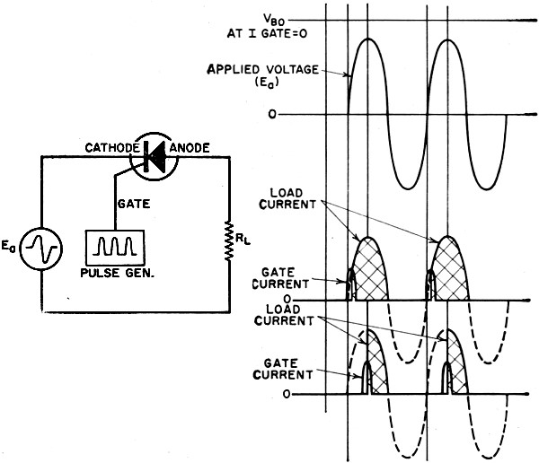
Fig. 5 - Typical specifications for various SCR packages. These types are suitable for use in home appliances. Principles of SCR Power Control To understand how the electrical characteristics of silicon controlled rectifiers are generally employed for power-control purposes, consider the simplified schematic of Fig. 6. Here the SCR is connected in series with a load resistance and an a.c. power source. A separate pulse circuit supplies positive-going trigger pulses to the SCR gate.
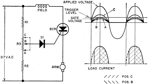
Fig. 6 - A simplified circuit which shows power control. The SCR is selected to have a VBO rating that is higher than the peak value of the applied a.c. anode voltage. This means that under conditions with no signal applied to the gate, the SCR will remain in the off condition at all times and no current will flow through the load (except for some slight forward and reverse leakage currents). If a gate trigger pulse of sufficient amplitude is applied at the beginning of the positive-going anode cycles, the breakover voltage of the SCR can be reduced to the point where breakover will occur almost at the beginning of the anode cycle. The SCR, therefore, is turned on and will remain in the on condition for the remainder of the positive half of the anode cycle even though the gate trigger pulse is removed. Load current will follow the positive-going anode voltage, being limited principally by the value of the load resistance. During the negative portion of the anode voltage, load current will be cut off entirely, irrespective of any gate signal. If the gate trigger pulse is delayed so that it occurs, for example, at the peak of the positive anode cycle, the SCR will conduct for only a quarter of a cycle. By introducing a variable phase shift between anode and gate signals, complete control can be achieved over the positive half cycle of anode voltage. For equipment whose output depends on the average value of the load current (such as the light from an incandescent bulb, the heat from a heating element, or the speed of a universal motor), this provides the means for controlling the output from zero to some maximum value. Of course, for a simple half-wave circuit the maximum output will not be as great as if both halves of the anode cycle were utilized. Maximum control can thus be obtained by using SCR's in full-wave or bridge circuits. Typical Circuits A simple SCR control circuit, in this case a motor-speed control for electrical appliances, is shown in Fig. 7.
Fig. 7 - A simple motor speed control circuit. In this circuit, the anode-cathode terminals of the SCR are connected in series with the motor field and armature across the 117-volt a.c. line. Resistors R1 and R2 in series with potentiometer R3 represent a voltage divider from which the gate signal is derived. Values for the resistive divider are calculated so that, with the variable arm of R3 in position A, the amount of gate current is not great enough for SCR triggering even at the maximum instantaneous anode potential. With the control advanced to point B, enough gate current would flow at the peak of the cycle to trigger the device. At that point, field current would flow during 90° of the applied voltage. At point C, the firing potential would be reached sooner so that load current would flow for perhaps 130° or more of the applied voltage. This circuit offers control over almost half of the positive-going portion of the applied voltage. During the negative half cycle, SCR current is cut off. Diode D1 is inserted in the gate circuit to block the application of excessive reverse current to the gate electrode which could result in damage. A more elaborate circuit, one that permits the control of both halves of the applied voltage cycle, is shown in Fig. 8. Here, a full-wave rectifier bridge is employed in such a way that the voltage applied to the divider and SCR circuit is pulsating d.c. comprising both halves of the input cycle. Operation otherwise is similar to the previous circuit. The utilization of the entire input cycle in this bridge circuit permits higher maximum motor speeds and smoother operation than obtainable in the half-wave configuration.
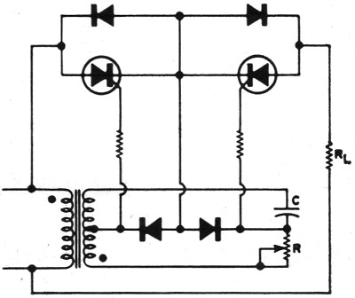
Fig. 8. Circuit that permits the control of both alternations. Diode across motor field protects circuit from reverse voltages. One advantage of SCR control is that the circuits often can be designed to accomplish additional functions. This is illustrated in the above designs, patented by Momberg and Taylor of Singer Mfg. Co., where the SCR is connected between the motor field and armature. In this type of connection, for all but the maximum-speed setting, voltage feedback from the motor tends to keep the motor speed constant under varying loads - an advantage that is of considerable importance in the power tool field. In each of these circuits, of course, the load may be a heat- or light-producing appliance provided that the current rating of the SCR is high enough to handle the required full-load current. Since the minimum conduction angle in the above circuits is 90°, these do not offer continuous control from zero to maximum. There are other configurations, however, that do provide this feature. One such circuit is shown in Fig. 10. With this type of connection, changing the setting of potentiometer R varies the phase angle between the SCR anode and gate voltages from zero to 180°, thus controlling the firing point of the SCR's over an entire half cycle.
Fig. 10 - Circuit permitting control over entire half cycle of applied voltage. In this circuit, the value of R must be at least ten times the reactance of C at the operating frequency. With a minimum-resistance setting of R, the gate circuits are connected across the lower half of the center-tapped transformer winding and the voltage applied to the gates of the SCR's is in phase with the anode voltage. The SCR's conduct for nearly 180° on alternate half cycles. With maximum setting of R, the reactance of C can be considered negligible and the gate circuits are effectively connected across the opposite half of the transformer winding. The voltage applied to the anodes and gates are nearly 180° out of phase and virtually no conduction takes place. With intermediate settings of R, conduction angles ranging from near zero to almost 180° can be achieved. Unijunction transistors and four-layer diodes (similar to SCR's but without the gate-trigger provisions) may be used to provide turn-on pulses for SCR circuits. Such devices are normally employed in relaxation oscillator circuits with variable pulse spacing so that triggering may occur at any point of the SCR anode cycle. A typical circuit using unijunction transistor triggering is shown in Fig. 9.
Fig. 9 - SCR controlled light-dimmer circuit. Although much simpler circuits can be used for this purpose, including the circuits previously shown for motor-speed control, this circuit provides a full range of light-brightness control. This arrangement employs a full-wave bridge rectifier, a zener diode (D1) to clip and regulate the voltage applied to unijunction transistor Q1, and an SCR. By varying the value of R2, the charging rate of C can be controlled so that the trigger pulse across R4 can appear at any point of each applied half-cycle. This results in complete control over the SCR. With SCR control, every electric light switch in the home becomes a potential light dimmer that provides continuously variable operation from full off to full on. A high-power bulb in a child's nursery may be adjusted to give plenty of light during play hours, but it can be turned down to just a glimmer for night-light purposes. In living and dining rooms, light dimmers can provide just the right degree of illumination to fit any mood and, for amateur puppeteers, the basement rumpus room can be converted into a theater, complete with theater as well as stage light dimming equipment. SCR control can increase the functions and conveniences of kitchen electrical appliances. Electric ranges with SCR control can match the infinite heat selection of gas equipment, electric toasters can become more efficient and far more reliable, electric mixers and blenders, automatic refrigerators and freezers, even dishwashers, can benefit from the variable current capabilities of SCR circuits. In the workshop, SCR circuits in electric power tools can convert a particular implement into a multi-purpose device. Drills and saws can be adjusted for just the right speed for virtually all types of materials and, with feedback circuitry, can provide constant torque irrespective of load. Soldering irons with heat control can be used for a variety of purposes other than soldering and every piece of electrical equipment that runs too fast, gets too hot, or burns too bright for a particular application can benefit. These applications, of course, are in addition to those where SCR's can replace relays or contactors in equipment where the reliability and ruggedness of semiconductor devices have decided advantages. While these advantages, with yesterday's high-priced SCR's, seemed rather vague, today they take on a new significance. And, for the electronics engineer and technician, the widespread application of SCR's in volume-produced electrical equipment promises another, as yet unexplored, field of operation with new opportunities for all.
Posted April 6, 2015 |
|