Just as modern high power semiconductor amplifiers are composed
of cascoded (connected in parallel) lower power amplifier units,
so too are super-high-power vacuum tubes. In the case of tubes,
a requisite number of triodes (typically) are arranged around
the perimeter of the tube enclosure with the inputs and output
connected to power dividers and combiners, respectively. Vacuum
tubes are still used in high power applications, although it
is rare that you will find them with glass enclosures; most
are metal and/or ceramic. Over-the-air radio and television
broadcasting stations are major users.
Richardson Electronics is a major distributor for these
types of tubes.
Super-Power U.H.F. Tubes
Cover Story
By R. E. Reed & A. C. Tunis
Electron Tube Div., Radio Corp. of America
Capable of producing millions of watts of pulse power,
these tubes are designed for the maximum amount of u.h.f.
power output from a single-envelope device.

The term "super-power" applied to a new family of grid-controlled
amplifier tubes, developed to meet increasing demands for
higher u.h.f. power output, is not a misnomer. These tubes,
which are capable of producing megawatts of pulse power
output and hundreds of kilowatts of average power output,
are particularly well suited to applications such as long-
and short-pulse long-range search radars and missile-tracking
radars, particle-accelerator power sources, broadband radars,
space-probe and satellite radars, satellite communications,
and r.f. power sources for special-process and heating applications.
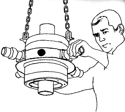
This new family of tubes includes the commercial types
RCA-7835 (shown on this month's cover being inserted into
an external resonant cavity), and RCA-2054, as well as several
modified developmental versions used in government-procured
or sponsored equipment. These tubes are the result of an
integrated program designed to produce the world's most
powerful u.h.f. power-output device in a single envelope.
For example, the 7835 can produce 5-million watts of pulse
power at 250 mc. (See Table 1)
Maximum Ratings*
Peak Positive-Pulse Plate Voltage. 65,000 volts
max.
Peak Negative Grid Voltage .............. 500 volts
max.
Peak Plate Current ......................... 325
amps max.
D.C. Plate Current .......................... 3.25
amps max.
Plate Input (average) .................. 212,000
watts max.
Plate Dissipation (average) ......... 150,000 watts
max.
*For frequencies up to 300 mc. and for a maximum
"on" time of 25 microseconds in any 2500-microsecond
interval.
Typical Operation**
Peak Positive-Pulse Plate-to-Grid
Voltage ............................. 34,000
60,000 v.
Peak Cathode-to-Grid Voltage ..... 100
300 v.
Peak Plate Current ..................... 260
280 a.
D.C. Plate Current ....................... 2.6
2.8 a.
Peak Driver Power Output ...... 150,000
200,000 w.
Useful Power Output at Peak of
Pulse (approximate) ... 5,000,000
10,000,000 w.
**In a cathode-drive circuit, with rectangular-waveshape
pulses, at 250 mc., with a duty factor 0.006, and a
pulse duration of 25 microseconds.
Table 1. Operating characteristics of
type 7835 super-power triode (shown on cover) as plate-pulsed
class B power amplifier.
Design Philosophy
Fundamentally, the new family of super-power tubes combines
a number of triode units in parallel in a common ceramic-metal,
water-cooled envelope. This is done to provide maximum emission-current
capability without exceeding a practical electrical length
for u.h.f. operation. A total of 96 triode units provide
the total electron current required. The cross-section of
the active region in Fig. 1 shows the relative positions
of the elements in each unit triode and the relation of
each unit to adjacent units.
The plate, which is centered about the electronically
active region of the tube on insulating low-loss ceramic
bushings, forms the outer conductor of a portion of a coaxial
output circuit located within the tube. The plate face is
made of oxygen-free high-conductivity copper which provides
the high thermal conductivity necessary to conduct the heat
dissipated on the plate face by impinging electrons to the
cooling water on the reverse side.
The grid consists of 0.003-inch-diameter pure tungsten wire
wound around the circumference of the grid cylinder. Each
grid wire is located in tiny slots across the radial fins
that extend outward from the grid block between the cathode,
as shown in Fig. 1. A rolling operation firmly fastens the
grid wires in position and molds the edges of the fins around
the wires to provide the necessary electrical and thermal
contacts. The fins are an integral part of the water-cooled
grid cylinder.
The thoriated-tungsten filamentary cathode strands have
rectangular cross-sections with appropriate reduction in
area at either end to compensate for thermal conduction
to the supporting structures. Approximately 70 amperes of
filament current is required to heat each strand to the
normal operating temperature. The total filament power required
for long-pulse and c.w. service is 6800 amps at 3.5 volts.
For short-pulse service, 1800 amps at 1.3 volts is used.
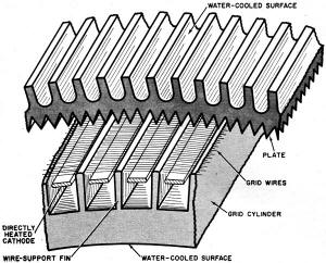
Fig. 1. Cross-section of a portion of
the active region of the tube showing the relative positions
of plate, grid, and cathode.
Mode of Operation
These super-power u.h.f. amplifier tubes are designed
for use with external coaxial-cavity resonator circuits,
as shown on the cover, and require no neutralization in
grounded-grid operation. The structural elements are arranged
for r.f. operation in the fundamental coaxial mode with
a voltage maximum occurring at the center of the electronically
active portion of the tube. Such an arrangement permits
double-ended operation with portions of two adjacent r.f.
quarter-wavelengths in the active region of the tube. The
double-ended arrangement provides twice as much plate current
from a given peak-drive voltage, and power output may be
as much as four times that obtained from a single-ended
tube with the same load resistance. The d.c. supply voltage
would have to be increased accordingly.
Double-ended construction also permits the tube structure
to be considerably longer physically for a given operating
frequency. Consequently, increased area is available for
dissipation of d.c. power that is not converted to r.f.
power, and structural limitations are less severe than those
imposed by the compactness required for a single-ended device.
In addition, a more rugged structure can be achieved by
avoiding the cantilever support of tube elements so common
in single-ended power tubes.
Applications
At present, these new super-power u.h.f. amplifier tubes
are being used in seven types of government end-use equipment,
including most of the types listed in the first paragraph.
All of these applications use external-cavity circuits that
were successfully designed by the equipment manufacturers.
Careful cavity-circuit design to reduce voltage gradients
and to locate spurious modes outside of the operating-frequency
region has resulted in reliable operation at power outputs
of 5,000,000 watts. Although it is premature for reports
of extremely long life, one tube has already accumulated
6000 hours of service life and another has operated for
4800 hours.
Acknowledgements
Much of the tube development work described was done
under the sponsorship of the Air Force. The Air Research
and Development Command of the Rome Air Development Center
contracted originally with RCA to engage in an electron-tube
development program that produced the new design concept.
Subsequent Air Force-sponsored programs for the device resulted
in the commercial RCA-7835 and RCA-2054. Much of the credit
for these developments should be given to the team efforts
of numerous other engineers and technical specialists at
RCA.
1. Vennard, J. K.; "Fluid Mechanics," 1947, p. 126.
Hoover, M. V.; Advances in the Techniques and Applications
of Very-High-Power Grid-Controlled Tubes." Proceedings of
International Convention on Microwave Valves, May, 1958.