|
March 1971 Popular Electronics
 Table of Contents Table of Contents
Wax nostalgic about and learn from the history of early electronics. See articles
from
Popular Electronics,
published October 1954 - April 1985. All copyrights are hereby acknowledged.
|
"Praetersonic" - now that's
a word you don't run up against very often. It is a combination of
praeter* (beyond)
and sonic (related to sounds), or what more familiarly is called ultrasonic. If
fact, praetersonics was the early term given to surface acoustic wave (SAW) piezoelectric
devices. Amazingly, even as far back as the early 1970s, SAW filters were being
fabricated that worked in the 40 MHz realm. This 1971 Popular Electronics
article does a really nice job of introducing the basics of SAW and BAW (bulk acoustic
wave) technology at the time it was coming into the mainstream. Lots of hurdles
still needed to be overcome, like high insertion loss, difficult to control impedances
and internal signal reflections, etc. As with many new technologies, pundits cast
hopeful prediction for having possibly found the panacea for many of the days' current
problems. To wit, "Acoustic-wave devices may finally hold the key to flat-screen
TV." One thing for sure is that it is hard to imagine what our cellphones and other
wireless devices would look like - or if they would even exist - without SAW and
BAW filters and resonators.
* Also written as "preter."
New Acoustoelectronic Components Replace Conventional Tuned Circuits
 By James R. Fisk, W1DTY By James R. Fisk, W1DTY
Within 3 years a wholly new technology has been quietly developed that may lead
to the perfection of flat-screen TV, faster computers, better i-f strips, improved
radar filters, etc. This is a report on what has been referred to as the "most significant
development" since the transistor. The devices involve acoustic waves traveling
on the surface of piezoelectric substrates.
There is a broad interface between the sciences of acoustics and electronics.
While most people think this mingling is in the area of voice radio communications
and stereo sound reproduction, laboratories are quietly developing a brand-new acoustoelectronic
component - the surface-wave filter and amplifier. Recent advances promise that
the impact on the design of electronic equipment will be equivalent to that of solid-state
components.
The new technology goes by a variety of names: praetersonics (meaning beyond
sonics), acoustoelectronic, surface waves, etc.; but it involves nothing more complex
than honest-to-goodness acoustic waves travelling on the surface of miniature chips
of piezoelectric substrates.
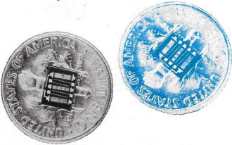 One company - Zenith Radio Corp. - has already
developed acoustic-wave 40-MHz i-f filters for color TV. They are only 0.15 in.
square and can be cascaded to synthesize the proper i-f response for color TV signals.
Aside from small size, the filters have the advantage of being permanently tuned.
Once set, they cannot drift off frequency. One company - Zenith Radio Corp. - has already
developed acoustic-wave 40-MHz i-f filters for color TV. They are only 0.15 in.
square and can be cascaded to synthesize the proper i-f response for color TV signals.
Aside from small size, the filters have the advantage of being permanently tuned.
Once set, they cannot drift off frequency.
In other laboratory experiments with praetersonics, high-gain r-f amplifiers,
oscillators, resonators, signal couplers, waveguides and delay lines are being developed.
Electronic navigation and communications systems employ complex signals that
must be rapidly processed and analyzed. Delay lines are essential to this process
since they can store the signals and compress, expand, or decode their waveforms.
These functions are usually handled by lengths of strip line or coaxial cable which
add bulk, are inefficient, and often introduce losses. However, praetersonic delay
lines - the first practical application of acoustic-wave technology - offer a compact
way of obtaining lossless, undistorted delays up to many microseconds duration,
with easy access to the signal for processing anywhere along its travel.
Actually, the first acoustic-wave delay lines employed bulk acoustic waves traveling
through the interior of a piezoelectric crystal.
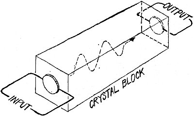
In its simplest form (see Fig. 1), the bulk system has a pair of transducers
mounted on opposite ends of a crystal. The input transducer, excited by an r-f signal,
beams acoustic energy through the crystal. The output transducer picks up the energy
and converts it into a usable electrical signal. The delay is simply the time the
signal remains in the block.
Bulk delay lines have one major disadvantage: it is almost impossible to tap
or otherwise manipulate the signal while it is in the crystal block. Surface acoustic
waves, signals that travel on the surface of the crystal instead of through the
crystal block, do not suffer from this shortcoming. The signal can be sampled anywhere
along its travel, after any duration, and the delayed waveform will be identical
to the input waveform.
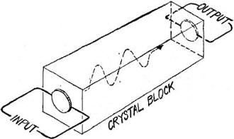
Fig. 1 - Early acoustic-wave delay lines employed bulk acoustic
waves which traveled through interior of crystal block from input to output transducer.
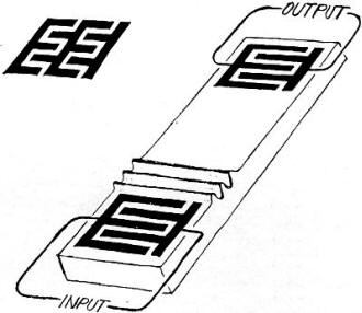
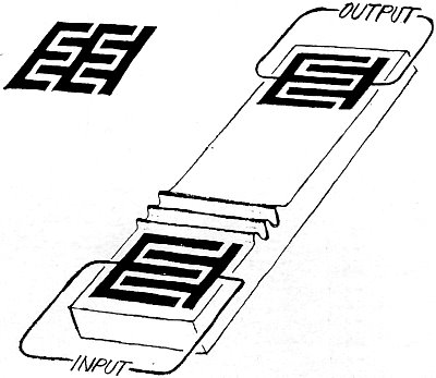
Fig. 2 - Modern praetersonic devices have interdigital transducers
which translate electrical input signals into physical waves (shown greatly exaggerated)
which travel along surface of crystals. Numerous impedances can be obtained by subdividing
interdigital electrodes as shown at upper left.

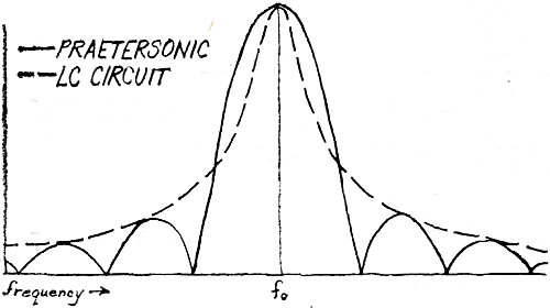
Fig. 3 - Curves of conventional LC tuned circuits and praetersonics
devices are basically similar.

Fig. 4 - Equivalent circuit of interdigital transducer is
a series resistance-capacitance network.
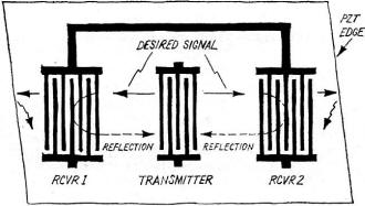
Fig. 5 - To reduce losses and minimize echoes, two receiver
transducers are used and substrate edges are cut at angles.
The basic surface-wave device is the delay line shown in Fig. 2. It consists
of a piezo-electric substrate (such as quartz) and input and output transducers.
The input transducer is an "antenna" which converts the electrical signal into an
acoustic wave which travels on the surface of tae substrate. At the other end of
the crystal, the wave is converted back into an electrical signal by the output
transducer.
The wave propagates rather slowly across the surface of the substrate, the delay
being determined by the spacing between the transducers. A 1-inch spacing corresponds
to a delay of about 8 microseconds.*
The design of the input and output transducers is extremely important since the
mass and shape of the electrodes have loading effects which influence efficiency.
The size of the transducer also affects bandwidth. The interdigital structure consists
of two separate arrays of metal electrodes resembling interlaced fingers.
The r-f signal across the input transducer interacts with the piezoelectric substrate
on the surface of the crystal, in opposite directions and at right angles to the
electrodes. Since the acoustic wave receives an in-phase energy boost at each electrode,
the wave generated by one finger pair builds up maximum acoustic power as it travels
through succeeding finger pairs.
The interdigital transducer functions with relatively low loss over a wide dynamic
range. By changing the number of fingers, the bandwidth can be tailored for nearly
any application. Finger size and spacing determine the center frequency. So the
basic acoustic-wave delay line becomes a resonator that can be substituted for LC
tuned circuits. The response curves for a typical surface-wave resonator and a typical
LC tuned circuit are shown in Fig. 3. The curves are basically similar.
The only significant difference between the simple delay line shown in Fig. 2
and a resonator is the spacing between the input and output transducers. In the
surface-wave resonator, the transducers are relatively close together (about 0.05"
in the 40-MHz i-f filters made by Zenith).
The input impedance of the surface-wave device is determined by the number of
electrode fingers and the length of the pattern. Also, a considerable impedance
range is available by subdividing the electrode pattern (see Fig. 2 upper left).
In practice, for the PZT material (lead zirconate titanate) used by Zenith, impedances
between 20 and 1000 ohms are easily obtainable at 40 MHz.
The equivalent circuit of an interdigital transducer is a series resistance-capacitance-reactance
network as shown in Fig. 4. In the diagram, Ra is the radiation resistance,
Xa is the radiation reactance, and Ct is the transducer capacitance. Inductance
L in the matching network compensates for Ct at the frequency of maximum response.
This inductance reduces mismatch losses and has an influence on the shape of the
passband.
In general, the tuning coil increases bandwidth. Tuning it slightly off the frequency
of maximum response skews the curve of the passband. This factor can be used to
advantage when tailoring the passband to a specific requirement, such as the video
i-f of a color TV receiver.
The interdigital transducer generates acoustic power that radiates in two directions.
Hence, the transducers inherently have at least 6 dB insertion loss since half the
power is radiated in the wrong direction. Also, if not properly terminated, this
backwave can be reflected at the edge of the substrate into the delay line where
it might show up as a spurious signal in the output.
To avoid the echo created by the backwave, wax is often deposited on the substrate
edge to absorb the backwave energy or the surface is etched behind the transducer
to scatter the backwave. Zenith cuts the substrate at an angle so that reflection
of the backwave is away from the active surface of the resonator.
In addition to backwave losses, a sizable portion of the signal arriving at the
output transducer is reflected back to the input transducer, where it is again reflected.
Each reflection results in a 6-dB drop in power level. This spurious echo, called
the triple-transit signal, is seen at the output 12 dB below the original signal
which made the trip only once. In the surface-wave i-f filter, this delayed and
attenuated replica of the original signal manifests itself as a ghost on the TV
screen.
Because the acoustic surface is not 100% efficient, there are transmission losses
that must also be added to the losses created by the echo signals. Therefore, total
losses can add up to 15 dB with tuning coils and 21 dB without the coils. A 3-dB
reduction in these figures can be obtained by employing the double receiving pattern
illustrated in Fig. 5, decreasing total insertion loss by lowering the directional
loss of the backwave.
In Zenith's i-f filters, careful design, including the use of shield lines between
transducers, has been successful in keeping reflections 30 dB below the desired
signal. This appears adequate for color TV i-f strips.
Aside from passband shaping provided by the external tuning coil, the response
can be broadened by increasing the terminating impedance. These two variables arc
used by the designer to shape the response curve to a given application.
Three cascaded surface-wave resonators provide the required response curve for
TV video in the Zenith filters. The connections between the resonators are shown
in Fig. 6. Resonator A provides out-of-band rejection and moderate attenuation
of the sound carrier. Resonators Band C provide a video notch at 41.25 MHz and,
with resonator A, provide the proper passband, including a notch at 47.25 MHz. Resonators
A and D work together to provide the proper level between the sound and picture
carriers.

Fig. 6 - Filter hookup for TV i-f strip and audio i-f take-off
is shown at top. Directly above, waveform produced by filters (dashed line) is shown
superimposed on desired wave shape.

Fig. 7 - Integral amplification from acoustic wave devices
is obtained from addition of a chip of n-type semiconductor material mounted over
substrate.
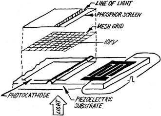
Fig. 8 - Acoustic-wave devices may finally hold the key
to flat-screen TV. In illustration, surface wave stimulates emission from photocathode.
Emitted electrons pass through B+ boosted grid and are accelerated to produce light
on a phosphor screen.
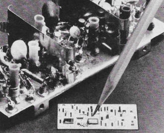
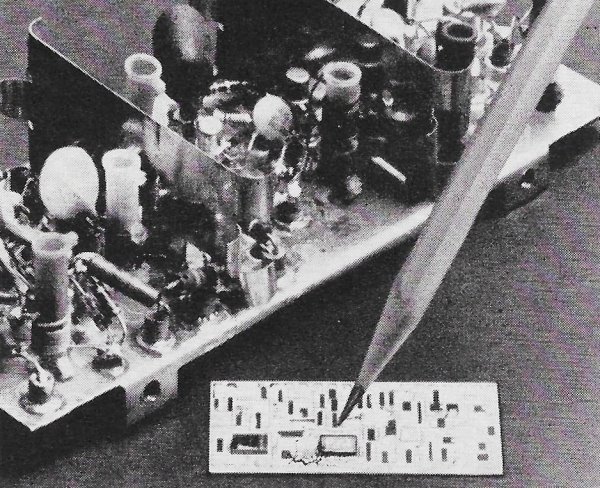
Zenith's thick-film circuit (foreground) is designed to replace
modern bulky i-f strips (background). Ultrasonic filter at pencil tip will reject
frequencies other than those desired.
The measured video response obtained by cascading the three surface-wave resonators
comes very close to fulfilling the desired color-TV i-f response as shown. It ran
be seen that the praetersonic surface wave filter provides the required passband
as well as the necessary traps at the desired locations.
When the praetersonic i-f filter was substituted for a standard tuned-circuit
i-f strip in a Zenith color TV receiver, it produced a picture of good quality with
no noticeable ghosting. The amplifiers used with the experimental filter were of
the wideband variety with at least a 60-MHz bandwidth.
Although the experimental Zenith filters used fairly conventional solid-state
amplifiers, future designs will probably incorporate a surface-wave amplifier that
is an integral part of the resonator. For useful praetersonic amplification, the
piezoelectric characteristics of the substrate should be separated from its semiconductor
properties. Since the electric field associated with an acoustic surface wave extends
out of the surface of the crystal, it can interact with the electrons in a de-powered
semiconductor placed a small distance above the crystal as shown in Fig. 7.
The basic items for the surface-wave amplifier are an optically flat piezoelectric
crystal and an n-type silicon semiconductor. Amplification results from the interaction
between drifting electrons in the n-type silicon and the piezoelectric field in
the surface-wave device. For minimum signal distortion, the two crystals must be
acoustically separated.
But for maximum field-electron interaction, the air gap must be a small fraction
of the acoustic wavelength. In a typical 100-MHz praetersonic amplifier, an air
gap of about 200 millionths of an inch is used. This spacing can be obtained by
a layer of silicon-dioxide that has been vacuum-deposited on the surface of the
substrate.
Since the piece of n-type silicon is fairly large, it has high resistivity and
requires a 2000-volt power supply for high gain. If the silicon is made very thin
and broken into segments, however, 30 dB of gain is possible with a 180-volt supply.
By adjusting the supply voltage, this system can provide either gain or attenuation,
allowing the output signal a range in excess of 100 B. When the applied voltage
is low, the surface wave is attenuated because energy flows from it to the slower
moving electrons in the semiconductor. As the voltage increases beyond the point
where electrons are moving faster than the surface wave, energy is imparted to the
wave, resulting in gain.
The surface-wave amplifier has a built-in bonus. Reflections between the input
and output transducers are attenuated so that the triple-transit signal is greater
than 60 dB down from the desired signal. And the high-gain flexibility means that
switches and modulators with greater than 90 dB of dynamic range are possible.
The acoustoelectronic amplifier can perform many other functions besides variable
amplification. If the amplifier is operated in its nonlinear saturated region, it
functions as an effective r-f mixer. Using external feedback, stable oscillation
results. It is feasible to conceive a 500-MHz amplifier, mixer, and low-frequency
i-f strip all operating on a single substrate.
With the arrival on the scene of the acoustoelectronic amplifier, it appears
that conventional tuned LC systems have a serious competitor, at least in the frequency
range from 30 to 500 MHz.
Looking into the future, praetersonics may hold the key to flat-screen TV picture
tubes if current development work pans out. The basic principle for the flat screen
is shown in Fig. 8. The electric field between crests of an acoustic surface
wave is sufficient to control emission from a semiconductor photocathode. To use
this voltage, a photo-emissive material is deposited on the piezoelectric substrate.
When suitably lighted, the photocathode emits electrons which are accelerated by
a 10,000-volt field to produce visible light on a phosphor screen.
An input pulse produces a transverse line of light that moves across the phosphor
screen, providing the horizontal scan. Vertical scan can be obtained. with another
acoustic beam applied simultaneously at right angles to the first beam.
Surface acoustic waves also have potential applications in high-speed data processing
with bit rates in excess of 100 MHz. In this scheme, digital-logic bits in the form
of acoustic pulses pass through an arrangement of transducers which perform the
logic operations by providing outputs of zero or high-amplitude pulses. These acoustic
wave pulses are then converted into pulsed r-f waveforms for further processing
by an output gate circuit.
Logic inverters and NAND and OR gates have already been operated at 120 MHz with
a 5-MHz bit rate. And 100-MHz bit rates are anticipated shortly.
Another important application of praetersonics is in the field of high-resolution
radar. Current radar displays employ bandwidths of less than 10 MHz. But for high
resolution, bandwidths should be on the order of 500 MHz. Broadband praetersonic
delay lines can be used between the radar and the display to store and recirculate
the signals so that they can be sampled and displayed at the lower frequency.
 Since the acoustic wavelength is so much
smaller than the free-space wavelength, many signal-processing techniques that have
been previously confined to the microwave region can now be translated to the lower
frequencies. Acoustic waveguides operating at 5 MHz are possible, as well as are
strip-line-type directional couplers and other hardware familiar to the microwave
technician. A lab-built directional coupler for 5 MHz, for example, provides up
to 20 dB of isolation and its total length is only 6 inches. Since the acoustic wavelength is so much
smaller than the free-space wavelength, many signal-processing techniques that have
been previously confined to the microwave region can now be translated to the lower
frequencies. Acoustic waveguides operating at 5 MHz are possible, as well as are
strip-line-type directional couplers and other hardware familiar to the microwave
technician. A lab-built directional coupler for 5 MHz, for example, provides up
to 20 dB of isolation and its total length is only 6 inches.
Although praetersonics is a new technology, it has evolved from theory to practical
hardware in less than three years. It is difficult to tell if we can expect the
same rate of progress in the future, but praetersonics promises to have at least
as much impact on electronic circuitry as did the introduction of the transistor.
It is now only a matter of time before this prediction becomes reality. Both waveforms
are basically similar.
* Until recently, praetersonics was known as "microwave acoustics" due in part
to the fact that early work in the field concentrated on devices for VHF and microwave
applications. But the term "micro" is also associated with the micron wavelength
of an acoustic wave on the surface of a piezoelectric crystal. At 30 MHz, for example,
a 100 micron or 0.004" wavelength is possible because acoustic waves travel 100,000
times slower than do radio waves!
|