|
March 1958 Popular Electronics
 Table
of Contents Table
of Contents
Wax nostalgic about and learn from the history of early electronics. See articles
from
Popular Electronics,
published October 1954 - April 1985. All copyrights are hereby acknowledged.
|
Pliers of the amateur radio
hobby have since the beginning put forth a lot of effort training fledgling entrants
in the realm of electronics and communications. Up until the latter part of the
last century, there were a number of magazines - Popular Electronics among them
- that would regularly print articles covering the basics of electronics. Other
than the ARRL's QST magazine,
it seems maybe Nuts and
Volts is the only monthly still in print that you can go to for such information.
I suppose it was inevitable with the emergence and now domination of the Internet
as a source for most knowledge. The "Among the Novice Hams" column in Popular
Electronics often included short primers on subjects like the basics of capacitors
and inductors. Here is one on inductors from March 1958. The basics still apply.
Among the Novice Hams
 By Herb S. Brier,
9EGQ By Herb S. Brier,
9EGQ
In the January column, as part of our discussion of the basic electronic theory
on which the General / Conditional / Technician license examination is based, we
talked about capacitance and capacitors. This month, we'll cover inductance and
inductors, which are also referred to as coils, chokes, and reactors. First let's
learn a bit about current and magnetism before taking up inductance itself.
Current and Magnetism. Imagine that a source of direct current, such as a battery,
is connected across the ends of a length of wire or other conductor. An electric
current, which consists of electrons in motion, will flow through the wire. If we
bring a magnetic compass near the wire, the compass needle will be deflected from
its normal position. The greater the current flowing through the wire, the more
the needle will be deflected. If we reverse the battery terminals, it will be deflected
in the opposite direction.
We have shown that electrons in motion (electric current) in a conductor generate
a rotating magnetic field around the conductor. We have also found that the direction
in which the electrons are moving determines the direction of rotation of the magnetic
lines of force. According to the "left-hand rule," when a conductor carrying current
is grasped in the left hand with the thumb pointing in the direction in which the
current is flowing (towards the positive terminal), the fingers point in the direction
of rotation of the magnetic field.
If we substitute a sensitive microammeter for the battery across the ends of
the conductor and rapidly move a powerful permanent magnet across the conductor,
the meter pointer is momentarily deflected. The direction in which the magnet is
moved determines the direction in which the meter pointer is deflected. The speed
of the magnet determines how much the pointer is deflected.
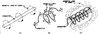
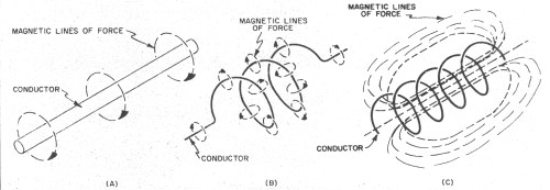
Fig. 1 - How magnetic lines of force around a conductor
carrying current (A) are concentrated by winding the conductor into a coil (B);
total magnetic flux path around the tightly wound coil is shown in (C).
Thus, a magnetic field moving across a conductor induces (causes to flow) a current
in the conductor. A current will also be induced in the conductor if the magnet
is held still and the conductor is swept across its poles.
The magnitude of the effect is small in a straight length of wire. If the wire
is wound into a coil like thread on a spool, the effect is greatly increased. Then
the magnetic lines of force around the wire act upon each turn and on adjacent turns
as well. Figure 1 illustrates this action two-dimensionally.
If we insert a soft iron core inside the coil, even more current flow takes place,
because the magnetic lines will travel through the iron much easier than through
air. Consequently, the iron core concentrates the magnetism around the turns of
the coil.
Self Inductance
Suppose we connect a coil containing thousands of turns of wire wound around
an iron core, a source of direct current, a voltmeter, an ammeter, and a switch,
as shown in Fig. 2. When the switch is closed, the voltmeter immediately indicates
the full battery voltage across the coil terminals. But the ammeter pointer moves
slowly up to a position determined by the resistance of the wire in the coil and
the applied voltage.
When the switch is opened, however, the ammeter pointer immediately drops back
to its zero position, but the voltmeter pointer flips up far beyond its previous
position before it drops back to zero. There will also probably be quite a large
spark across the opening switch contacts.
What happened? When the switch is first closed and current starts to flow into
the coil, a strong magnetic field starts to build up around the coil. This expanding
magnetic field is moving; therefore, it builds up an electromotive force of its
own in the coil. This induced electromotive force is exactly opposite to the applied
electromotive force. Consequently, it opposes the flow of current into the coil-but
it cannot cut off the current completely. If it did, there would be nothing to generate
the magnetic field. So the current slowly increases to its steady value and supports
a steady magnetic field around the coil, but the process does take time.
When the switch is opened, the incoming current drops instantly to zero and kicks
the props out from under the magnetic field, which is thus forced to collapse instantaneously.
While it collapses, the energy it contains is instantly converted back into an electromotive
force in the coil, which builds up in voltage until it is sufficient to arc across
the open switch contacts.
These effects are due to the inductance of the coil, which is measured in henrys.
By definition, a change of one ampere per second in the amount of current flouring
through an inductance of one henry generates an electromotive force of one volt
in it. The technical name for a coil containing inductance is an inductor. In radio
work, the terms millihenry (0.001 henry), abbreviated mh., and microhenry (0.000001
henry), abbreviated μh., are also used.
Applying A.C. Figure 3 shows what happens to the current and voltage in an inductor
if an a.c. generator is substituted for a d.c. generator.
For simplicity, let us assume that the a.c. generator voltage is maximum (point
A) when we close the switch. Immediately, this voltage tries to force current through
the inductor. But zip! The resulting magnetic field immediately generates a counter
voltage in the inductor, which sharply limits the amount of current that can flow
into it. However, as time passes, the generator gradually forces more current into
the inductor, even though the generator voltage is decreasing at the same time,
until 1/4 cycle or 90° later (point B), the current reaches its maximum value, just
as the generator voltage has decreased to zero.

Fig. 2 - Theoretical circuit used to illustrate the meaning
of inductance as discussed in the text.
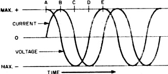
Fig. 3 - Current and voltage relationships in an inductive
circuit when alternating current is applied.
Immediately, the a.c. generator voltage starts increasing in the opposite (negative)
direction and tries to force a current through the inductor in that direction. But,
as soon as the current tries to reverse direction, the magnetic field generated
by the current flowing in the original direction starts to collapse, and its energy
is converted back into an electromotive force that tends to keep the current flowing
in the original direction.
At first, the electromotive force from the collapsing field is strong; so the
current is high. As the cycle continues, however, this energy is used up, while
the generator voltage is increasing. Thus, at the end of 1/2 cycle or 180° (point
C), the current has decreased to zero, just as the generator voltage reaches its
maximum negative value.
At this point, current starts flowing into the inductor in the opposite direction,
and the action of the current and voltage is like that of the previous half cycle.
At the end of a complete cycle (point E), the current and voltage relations are
exactly as they were when the switch was closed. These series of actions continue
as long as alter-nating current is fed into the inductor.
Inductive Reactance. Obviously, inductance opposes the flow of alternating current
through it. This opposition is called inductive reactance and is measured in ohms.
The formula for calculating it is:
XL = 2 π FL; where π (pi) 3.14, F is the frequency in cycles per second,
and L is the inductance in henrys. The formula is also correct if the frequency
is expressed in kilocycles and the inductance in millihenrys, or the frequency in
megacycles and the inductance in microhenrys.
Don Jensen, KN6VXM, worked the 48 states and Europe with a home-brew 6146 transmitter
running 50 watts. Now he uses a new Johnson Ranger transmitter.
An example will show that there is nothing mysterious about the formula. Question:
What is the inductive reactance of a 10-henry choke (inductor) at a frequency of
60 cps? Answer: XL = 2 X 3.14 X 60 X 10 = 3768 ohms. At 600 cycles, its
reactance is 37,680 ohms. Inductive reactance is directly proportional to frequency
and inductance. This is just the opposite of capacitive reactance, where the reactance is inversely
proportional to frequency and capacitance. Another difference between inductive
and capacitive reactance is that, in a purely capacitive circuit, the current leads
the voltage by 90°, while in a purely inductive circuit the current lags the voltage
by 90°.
Posted May 17, 2021
(updated from original post on 8/13/2012)
|