|
November 1966 Popular Electronics
 Table of Contents Table of Contents
Wax nostalgic about and learn from the history of early electronics. See articles
from
Popular Electronics,
published October 1954 - April 1985. All copyrights are hereby acknowledged.
|
This article in a 1966
issue of Popular Electronics magazine presents a surprising and maybe
even counterintuitive (to
those uninitiated in antenna physics) result when measuring the radiation pattern of
a CB-type antenna mounted at various points on a car. If you were asked to make a
rough sketch of the radiation pattern when the antenna is mounted in the center of
the roof, center of the trunk, and on each of the front and rear and left and right
fenders, would yours look like those in the article (assuming an all-metal car)? Today, there are many electromagnetic radiation pattern simulators available to
help predict antenna performance in just about any scenario imaginable. Design
verification is then usually performed either in actual operational conditions, in
anechoic chambers, in TEM cells, or on outdoor test sites. Being able to accomplish
the initial simulation using highly refined software algorithms can save huge amounts
of money and time, just as with circuit simulation and PCB / enclosure layout. In
1966, only government, university, and large corporations had the resources to employ
large mainframe computers for the task, and even then the capability was
significantly less than what can be accomplished on an iPhone today. For the vast
majority of people, antenna radiation pattern testing was purely an empirical
exercise after making a best guess at fabricating a physical unit.
Antenna Placement Does Make a Difference!
 A Blindfolded Choice is No Choice at All A Blindfolded Choice is No Choice at All
By Robert L. Ruyle
W0FCH, KGI-3471
Every Ham or CB'er with a mobile rig should be
aware that antenna placement is equally as critical as selecting the mobile antenna itself.
Furthermore, neither the antenna nor the mounting position should be chosen independently
and without due consideration of the other. When a position is arbitrarily selected,
the results may be disappointing. If they are, many hams and CB'ers start grumbling about
the manufacturer of the antenna, or even the qualities of the transceiver, whereas the
fault is simply that not enough thought was given to the actual placement of the antenna
on the automobile body.
The Best Positions
No matter how you look at it, the best possible position for a
mobile antenna is in the middle of the roof of a sedan or station wagon. When mounted
in that position, the antenna "sees" the car body as a large mass of metal permitting
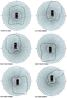
symmetrical radiation of your signals*. This effect is shown graphically in the drawings
at right. Note that the signal is fairly uniform in all directions, and turning the car
should introduce little signal fading or sudden signal drop-outs.
Many people cannot bring themselves to drill even a small hole in the middle of their
car roof**. If this is a consideration, or if you have a convertible, the next best position
is in the middle of the trunk lid. Of course, there will be a slight shift in the radiated
pattern as more metal is toward the front of the car than toward the sides or rear. However,
this causes little decrease in antenna efficiency. A second factor favoring the trunk
lid position is the height of the antenna. A center-of-the-roof-top antenna might be
troublesome if taller than 18" or 20". A trunk lid mounting permits use of a 40" antenna,
which increases the radiating efficiency over a broader bandwidth.

The illuminated areas above represent actual intensity and azimuth
measurements made at the testing facilities of Hy-Gain Electronics. The antenna used
was a full-length 108-inch whip tuned to 27.065 MHz. The roof-top mount is the best position
for all-round radiation, the left rear bumper just about the worst - except in its favored
direction where the lobe is substantially stronger. When the car is in motion and turning,
you can see why there are extreme variations in signal strength.
Fender Mounting
In an effort to simulate the appearance of cars
with commercial radiotelephone installations, a favored spot for many CB antennas is
either of the rear fenders. Shifting the antenna to either the right or left fender moves
the metal mass and, as can be seen in the antenna pattern drawings, maximum signal radiation
crosses diagonally through the car and out toward the opposite front fender.
Cowl or front fender mounting is becoming quite common - especially in view of the
availability of combination AM radio/CB antennas. Locating the antenna on either front
cowl reverses the metal mass distribution and the signal is pulled toward the rear of
the car and opposite to the front mounting.
Note that in all of the antenna pattern diagrams the scale is constant, and it is
really true that more signal is concentrated in the direction of the lobe. But, this
is a tremendous disadvantage if the car is moving and not aimed in the direction of that
lobe. For example, compare the left-rear-fender mounting pattern with the roof-top mounting
pattern. The signal strength through the right front fender is somewhat above that radiated
by the roof-top antenna, but from azimuth 130° to around 325°, the radiated signal
is substantially weaker.
Worst Possible Placement
Pity the unfortunate soul that cannot bring
himself to drill a hole in his car body. This fellow frequently chooses a rear bumper
mount. Results to be expected from such a mounting appear in the last drawing on page
65. The lobe pattern has been distorted and the car body is now absorbing some of the
radiated signal. If this pattern is compared with the left fender mounting pattern, it
is easy to see how positioning the base of the antenna lower on the car body has adversely
affected the pattern.
All of the tests illustrated in this article were made with the cooperation of Hy-Gain
Electronics and through the use of its testing facilities. The antenna used in each instance
was a 108" whip. All of the patterns would be influenced to some extent by the substitution
of a different antenna.
* Although reference is made in this article to transmitting, the identical effects
are observed when receiving a base station on your mobile rig. The lobe patterns then
show the extent and azimuth of maximum signal pickup.
** At least one manufacturer has a roof-top antenna that does not require a hole -
the antenna being held in place by a powerful circular magnet.
Posted July 5, 2023
(updated from original post on 5/7/2018)
|


