|
October 1972 Popular Electronics
 Table of Contents Table of Contents
Wax nostalgic about and learn from the history of early electronics. See articles
from
Popular Electronics,
published October 1954 - April 1985. All copyrights are hereby acknowledged.
|
This article
reporting
ongoing research for auto anti-collision systems and backup warning systems
appeared in a 1972 issue of Popular Electronics has only come to
practical fruition within the last decade and a half. High-end cars were
offering such equipment options in the early 2000s, but it has only been
commonplace since around 2010. 1972 components were still pretty large and power
hungry, and digital processing capacity and speed was significantly less
advanced as well. Bendix, one of the early developers of anti-collision systems,
estimated that the option on a new car might add about $200 to the price, which was a
really ambitious estimate, even considering that is the equivalent of
$1,4511 in 2023 money per BLS Inflation Calculator. The total
add-on cost of both anti-collision and backup warning systems on today's
automobiles probably doesn't even hit that figure, and the performance is orders
of magnitude better. The price and sizes of transmitter signal generators and
receiver sensors (antennas) are amazingly low, as are all the other system
components. Still, the research and development had to begin somewhere, and we
are grateful to those who had the vision and fortitude to take the first steps
that started us on the path to where we are today.
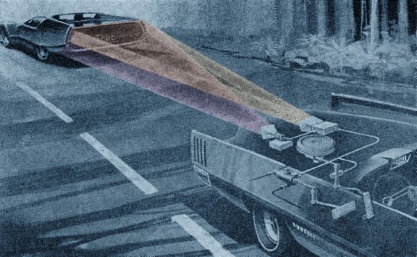
Anti-Collision Systems for Autos
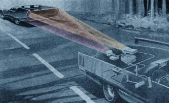
Fig. 3 - Ford system uses an invisible beam reflected by the
car in front.
Many People are Working on Ways to Prevent Accidents
By Fred W. Holder
Automatic speed control systems have been available as options on many American
cars for several years now. These systems permit a car to hold any selected speed
without driver control of the throttle. For drivers on the open road, they have
been a desirable convenience. However, when moderate to heavy traffic is encountered,
their convenience becomes marginal because the driver is constantly forced to override
the system to prevent collisions. Thus, with the addition of a system to automatically
slow down or speed up the vehicle to meet changing traffic conditions, automatic
speed control becomes an even more desirable - and practical - feature. Add automatic
braking when the distance separating two moving vehicles becomes critical, and you
have a real safety device.
Bendix, Ford, Sylvania, and others are working on systems which will refuse to
let your car ram another vehicle or will sound a warning if you are about to back
over something you cannot see. These systems are still in the development stages,
but they are expected to debut by the mid-1970's.
According to William Miron, Bendix Automotive Group President, the Bendix Adaptive
Speed Control (ASC) system has been under development for about 15 years. He estimates
that ASC will appear as an option in 1974 or 1975 (possibly earlier) cars. Estimates
show that this system will cost less than $200, a small price to pay for safety.
In addition to headway protection, warning systems are also under way to cover
the "back field." If you have ever backed over your kid's bike, you will appreciate
the extra feeling of safety that one of these back-up systems can give you.
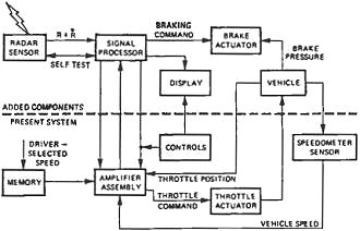
Fig. 1 - Bendix adaptive speed control system includes ranging
and braking.
The Bendix systems employ a radar beam as the detecting medium, while Ford has
opted for infrared radiation. Both, however, project an invisible beam forward or
backward to detect objects in the path of the vehicle. In the case of forward movement,
they apply brake or accelerator to maintain a specified safe distance ahead of the
car. Neither system requires the other object or vehicle to be equipped with a responding
device.
Headway Control
The Bendix ASC system is an extension of their electronic automatic speed control
system. In Fig. 1, the components below the dashed line comprise the basic speed
control system. Those above the line provide automatic headway control. The driver
actuates the system by pushing a speed-set button. The system memorizes the speed
selected and signals the throttle actuator to maintain this speed. If changing road
grade causes speed errors, the throttle is automatically adjusted to correct speed.
If another vehicle is overtaken, the radar measures the relative velocity and
range and sends them to the signal processor. The signal processor combines this
data with an input of the equipped car's speed and determines whether the throttle
or brakes should be applied to maintain a safe distance behind the other vehicle.
The equipped vehicle will continue to follow the lead car as long as it stays
under the driver-set speed. The system will never exceed the driver-set speed. However,
the driver can override the system at any time by manually applying the throttle
or brakes. If a car cuts in front of the equipped vehicle, its speed will be decreased
or the brakes will be applied to prevent a collision.
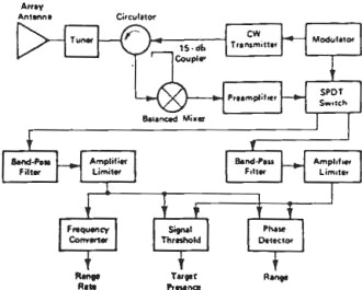
Fig. 2 - Diagram of Bendix radar system.
One of the problems encountered while developing the Bendix system was the design
of a low-cost radar suitable for automobile headway control. Because both range
and range rate were needed, a two-frequency CW approach was selected (see Fig. 2).
The transmitter is switched between two closely spaced frequencies, and the doppler-shifted
return signals are gated into separate channels.
The range is then a function of the relative phase between the two Doppler signals.
It is extracted by a phase detector. The range rate is determined from one of the
Doppler channels. A third output was needed to ensure that the processor would accept
only data with good signal-to-noise ratio level. This output, the threshold level,
determines the maximum range of the system.
In his paper "Application of Radar to Automobile Control and Sensing," W. P.
Harokopus of Bendix stated that he encountered two systems problems from the use
of a two-frequency radar. First, because Doppler shift is required to obtain range,
range information is not available when the range rate is reduced to zero. Second,
the system lacks range resolution and can suffer from multiple target effects. He
went on to explain, however, that experience with the system to date indicates that,
by providing the signal processor wall memory and smoothing, these obstacles are
overcome.
The first Bendix radar provided an operating range of 200-400 ft, depending on
the size and shape of the car involved. Small foreign cars are at the low end of
the range. This radar operates at 16 GHz with 50 mW of transmitter power. It uses
a standing-wave waveguide array antenna in place of the car's grille. The other
antenna components are standard microwave packages including a circulator, mixer,
coupler, and isolator. The transmitter is a Gunn oscillator.

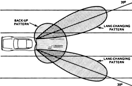
Fig. 4 - The Bendix rear-end warning system provides detection
for backing up or for changing traffic lanes.
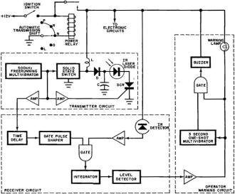
Fig. 5 - Simplified diagram of Ford back-up warning system showing
operation.
Bendix is devoting a considerable amount of their development work to ensuring
that the best fail-safe approach is selected for the production system. Their radar
has a self-test feature which, in the absence of a target, causes the modulator
to periodically audio modulate the oscillator. The system detects this modulation
through leakage. When the test signal is detected, it passes through the system
and is detected as if it were a target. If the test signal is not detected, a fail
light comes on and the system is deactivated.
The Ford system, designated Automatic Headway Control (AHC), is essentially a
computerized brake and throttle control unit similar to the Bendix system. On the
open road, AHC operates as a conventional speed-control device. When an AHC equipped
car approaches another vehicle from the rear, an optical beam is reflected from
the taillights of the car in front to an electronic processor which "reads" the
signal and changes accelerator and brake settings as needed to maintain a safe following
distance. The driver needs only to steer the car. The basic operating elements and
how the optical beam is used to detect another car's presence are shown in Fig.
3.
Back-Field Detection
Headway control alone does not cover some of the other critical driving hazards.
Studies have shown that blind spots in rear vision are contributing factors in many
accidents involving cars going in the same direction. Bendix, Ford, Sylvania, and
others are developing systems to warn the driver of the presence of traffic or objects
in these blind areas.
The Bendix system is composed of two lane-changing sensors and a back up sensor.
The sensors are CW homodyne radars. The approximate coverage o f each sensor is
shown in Fig. 4.
The antennas for the lane-changing sensors can be mounted next to the car's taillights.
The antenna patterns are designed to intersect adjacent lanes and illuminate the
blind areas. When a vehicle enters the illuminated zone, the driver is warned of
the presence of an approaching vehicle. (The radars are designed to ignore roadside
objects.) The lane-changing radars have a maximum range of 50-70 ft with a minimum
range response down to the center door post to cover the entire blind zone. The
antenna for the back-up sensor can be integrated into the rear bumper. The sensor
is inoperative until the car is placed in reverse. Visual and audible warning is
activated when the presence of any object is detected in the sensor's range of view.
The antenna pattern is centered on the road surface 10 ft behind the car with range
being 0-30 ft.
The Ford system uses an infrared laser diode, a semiconductor IR detector, and
an optical system mounted behind the rear axle to detect small objects up to 10
ft directly behind the car. It does not provide lane-changing protection. However,
it seems likely that this feature will be incorporated into a production model.
The system is activated when the automatic transmission lever is placed in park,
reverse, or neutral. When an object is detected, a warning buzzer sounds for 3 seconds
and a warning lamp lights up. The warning lamp remains lighted until the object
leaves the field of view or the system is deactivated by turning off the ignition
or shifting to drive.
A simplified diagram of the Ford Back Up Warning System is shown in Fig. 5. When
the ignition is on and transmission is in park, reverse, or neutral, the system
is activated. A self-starting 500-kHz free-running multivibrator provides the timing
for the system. When the multivibrator's output is near ground potential, the solid-state
switch closes and energy is stored in inductance L. The stored energy is transferred
to high-voltage capacitor C as the output swings positive, turning off the solid-state
switch.
At the beginning of the next cycle, the falling edge of the multivibrator signal
triggers the SCR into conduction. The positive charge in C is discharged very rapidly
through the laser diode and SCR, producing a 300-ns, 100-A peak current pulse to
fire the laser diode. At the same time, the SCR trigger signal is transferred to
a time-delay circuit in the receiver. This signal is then gated with return signals
from the IR detector.
The output of the gate is applied to an integrator which averages the gated receiver
signal over many cycles to reduce the effect of spurious signals. The output of
the integrator is compared to a preset threshold level. When the threshold is exceeded,
a signal is sent to a warning circuit. This signal triggers a one-shot multivibrator
and lights up a warning lamp. In addition, it is gated with the output (3-second
pulse) of the one-shot multivibrator and is used to energize a buzzer.
Sylvania's Wakefield Development Laboratory has developed a prototype ultrasonic
safety detector that automatically warns when another vehicle approaches from the
rear. The system can he installed in the rearview mirror or the rear light assembly.
It responds to noise generated by the engine and tires of a vehicle travelling at
least 35 mph within 25 ft of the detector. When an approaching vehicle is detected,
the system turns on a warning lamp.
Sylvania claims that their method of detection is better than forms using radiation
detection methods because it can discriminate between moving and stationary objects
along the roadway.
It appears that any of these collision prevention systems will be a boon to any
driver who encounters changing traffic and weather conditions. Optimistically, they
may one day eliminate the awful toll of lives lost on our nation's highways which
now stands at over 50,000 victims annually.
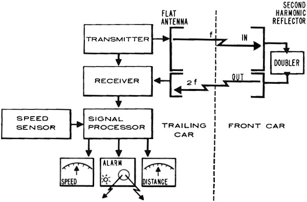
RCA System Uses Two-Way Radar
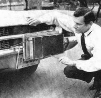
Radar transmitter is mounted on front bumper or behind grille
or license.
A collision prevention system designed by RCA uses a new look in vehicle radar.
A compact radar transmitter and receiver, measuring only 17 X 8 x 2 1/2 in., is
mounted on the front bumper (or behind the grille). It transmits a 100-mW, 9-GHz
signal which is vertically polarized with an effective beamwidth slightly less than
5 degrees. The receiving antenna is horizontally polarized.
The "target" vehicle uses a rear-mounted passive antenna that is 17 x 8 x 1/2
in., which accepts the signal from the following vehicle and, using special solid-state
diode microstrip filters, re-radiates the signal back to the following receiver
at twice the frequency. The return signal is horizontally polarized.
The difference in frequency between the transmitted and received signals is used
to determine the distance between the two vehicles. If the distance exceeds a predetermined
amount, a warning light and buzzer are turned on. The range is about 100 yards and
the narrow beamwidth of the transmitted signal enables operation only in one traffic
lane. Also, since the radar receiver is horizontally polarized and only accepts
signals at 18 GHz, oncoming vehicles fitted with the same system do not interfere.
Natural objects do not provide the proper return.

Transmitter, operating at 9 GHz, radiates a vertically polarized
signal which is picked up by passive antenna on the back of the target car. Signal
is then returned to following car at 18 GHz. This approach avoids background clutter.
Posted September 30, 2019
|