February 1960 Popular Electronics |
 Table of Contents Table of Contents
Wax nostalgic about and learn from the history of early electronics. See articles
from
Popular Electronics,
published October 1954 - April 1985. All copyrights are hereby acknowledged.
|
Integrated circuits are the
de facto standard of today, but 50+ years ago when this article was written for
Popular Electronics magazine, individual transistors were all that was
available to both hobbyists and professional engineers. Believe it or not, there
are still a lot of applications in modern products that use discrete transistors
for output stage drivers, buffers, and where parts costs might save a penny or two
in high volume production. There are also, of course, millions of circuits in existence
and in daily use that include transistors. This transistor tester will allow you
to do a simple check to determine whether a particular device is still working,
or whether some newer transistor might be a suitable replacement for one gone bad.
The truth is, though, that unless you just really like to build circuits, you can
buy a DMM with a built in transistor tester for $20- $30.
Build a Dual-Meter Transistor Tester
You can check both audio and power transistors with one easy-to-operate
unit.
By R. J. Shaughnessy
Sometimes you'll finish building a transistorized project and find that it doesn't
work. It's easy enough to recheck your wiring, but if you do and the unit still
doesn't work, then what? Were the transistors good before you put them in the circuit?
Were they burned out accidentally? It's obvious that you need a transistor tester
to check the transistors before you wire them into the circuit and to check them
again if the circuit stops working.
This tester measures the two important characteristics of almost all audio and
power transistors: current gain (Beta) and collector-to-base leakage (Ico). Only
transistors which have a 5-ma. maximum collector current cannot be tested with this
unit; see the manufacturer's data for special testing techniques for these low current
jobs.
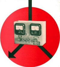
Two meters are built into the tester to allow the base current and the collector
current to be monitored simultaneously under various bias settings. This monitoring
feature enables a transistor to be tested under actual circuit load conditions.
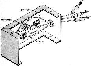
For maximum flexibility, no sockets were incorporated in the tester proper. The
transistor under test is simply connected by its leads to the tester terminals.
An adapter which plugs into the tester's binding posts can be built which will accommodate
the various types of power and audio transistor sockets. Parts used in the tester
and optional adapter are not critical. With all new components, cost of the tester
is about $15.
Observe polarity of diodes and capacitors in tester power supply
detail (left).
Transistor tester base current control R2 should be wired so
that maximum resistance is obtained when ganged switch S1 is open.
Tester adapter has two sockets accommodating power transistors
and smaller audio transistors.
Construction
of the tester is begun by mounting all the components directly on the cabinet.
Before mounting function switch S2, crimp all jumper leads to the switch terminals.
After the switch is mounted, connect and solder the remaining leads to it.
The transistor tester adapter can be built into the smallest Minibox that will
accommodate a standard three-lead transistor socket (in-line or circular type) and
a power transistor socket. When a transistor is being tested, the adapter's banana
plugs (which are connected to the appropriate pins on the transistor sockets) plug
into the tester's universal binding posts.
Tester Parts List
CI, C2, C3, C4 - I60-μf., 15-volt capacitor
DI, D2-1N91 germanium diode (Sylvania) F1 , F2 -1/2-amp. 3AG fuse (to fit PL1)
MI-0-1 ma. meter (Shurite 950-9300Z)
M2-0-100 ma. meter (Shurite 950-9307)
PL1-Fuse plug (El-Menco EL-32)
R1-6800-ohm, 1/2-watt resistor
R2-150,000-ohm potentiometer (IRC QI3-328)
R3-1000-ohm, 1-watt resistor
R4, R5-33-ohm, 1/2-watt resistor
S1-On-off switch mounted on rear of R2 (IRC 76-1)
S2-Four-pole, four-position rotary switch (Centralab PA-1013)
T1-6.3-volt filament transformer (Triad F-13X)
1-7" x 5" x 3" Minibox (Bud CU-2108A)
3-Five-way binding posts
2-Pointer knobs
2-Six-lug terminal strips
Testing for leakage is simple. Rotate function switch S2 to Leakage N-P-N or
Leakage P-N-P, depending on the transistor in question. Connect the transistor base
lead to the tester's emitter binding post. Then connect the transistor collector
to the collector binding post. Leave the transistor emitter lead unconnected. (The
transistor emitter is left unconnected for all leakage measurements.) Now turn on
the tester by advancing the Base Current potentiometer (R2). If the 0-100 ma. collector
current meter (M2) is not deflected, the leakage current is within acceptable limits.
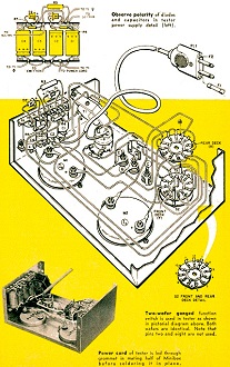
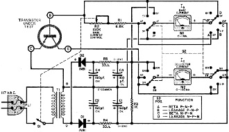
Two-wafer ganged function switch is used in tester as shown in
pictorial diagram above. Both wafers are identical. Note that pins two and eight
are not used.
Power cord of tester is led through grommet in mating half of
Minibox before soldering it in place.
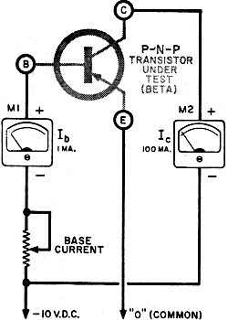
Current gain (Beta) test for n-p-n transistors is identical to
p-n-p test shown in simplified schematic but polarities of meters and power source
are reversed by switching S2.
You can safely measure the exact leakage current on the more sensitive 0-1 ma.
base current meter (M1). Turn off the tester and reconnect the transistor base and
collector leads to the corresponding tester binding posts. Do not connect the emitter
lead; keep the function switch in the "leakage" position. When you turn on the power,
you'll find that most transistors will give little - if any - deflection of the
0-1 ma. base current meter. Some low-leakage silicon units will give no perceptible
deflection at all.
ADAPTER PARTS LIST
1-2 3/4" x 2 1/8" x 15/8" Minibox (Bud CU 2100A)
1-Three-lead transistor socket
1-Power transistor socket (Motorola MK-10 or equivalent)
3-Banana plugs
If the transistor passes the leakage test, you can safely perform the current
gain (Beta) test. Current gain cannot be read directly on the tester, but Beta is
very easily found by dividing the collector current reading by the base current
reading.
The Beta test is made by setting S1 to Beta N-P-N or Beta P-N-P. Make sure the
power is off. Connect the transistor base, emitter, and collector leads to the corresponding
binding posts. Check the manufacturer's specifications for the maximum collector
current for the transistor under test and never exceed this value as read on the
0-100 ma. collector current meter. Now switch on the tester, but leave the Base
Current pot full counterclockwise. Record the base current and collector current
meter readings. Dividing the collector current by the base current will give you
one value for the Beta (current gain) of the transistor under test.
Now increase the base bias current with the Base Current potentiometer. This
will cause an increase in the collector current. Once more, record the meter readings
and compute the current gain. Continue this process until you have several values
for current gain.
Note that Beta is constant except at the higher collector currents; this is a
normal transistor characteristic. Check your computed values for the current gain
against the manufacturer's specs to see if the transistor is up to snuff.
You'll soon find that you'll have more confidence in the circuits you build and
trouble-shoot. Using the tester, you'll be able to give transistors a rapid checkout
and use them to best advantage.
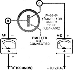
Leakage test effectively puts two meters in series with transistor
as shown in simplified schematic.
Polarities for n-p-n transistors are reversed as in Beta test.
Posted May 31, 2022
(updated from original post
on 12/7/2011)
|