Build an Electrolytic Restorer
|
|
Reading this kind of article takes me back to my days of building prototype circuits as an electronics technician at Westinghouse Electric's Oceanic Division in Annapolis, Maryland. It was without a doubt the best technician job I ever had. In fact, working with über engineer Jim Wilson and a few others is what really drove my determination to get an electrical engineering degree of my own. Laying out perf boards for resistors, capacitors, inductors, LEDs, switches, etc., and soldering all the point-to-point connections, then testing (and sometimes fixing miswirings) was a great gig. Drilling and labeling the project box with the dry transfer rub-ons in an attempt to make everything look as "real" as possible was always the goal. Prior to the engineering tech assignment, I spent a couple years building low volume (sometimes just one or two) specialty systems for the U.S. Navy. It involved a lot of PCB assembly (all through-hole components), wire-wrapping digital circuit boards, building cable harnesses on nail boards, and lots of other cool stuff. There were only about a dozen guys on each of the two shifts doing that work, making the days fly by as random discussions between everyone were held on just about any topic. The two inspectors were Westinghouse employees and good friends that also joined in, but man, they never let anything slide for any reason - every solder joint and W/W had to be perfect, wire bundles exactly routed per drawings with specified strain relief, and God help you if you accidently scratched the surface finish on anything ;-) Sometimes I wish I had just stuck with Westinghouse (now Northrop Grumman). Build an Electrolytic Restorer
By George J. Plamondon This project is used to restore (reform) the dielectric in electrolytic capacitors that have not been in use for an extended period of time. Half-wave rectified ac is switch-selected and applied to the capacitor. As the dielectric re-forms, the voltage increases indicating a reduction in current flow through the capacitor. Various reforming rates are available to the builder, as well as various applied voltages from 100 to 600 volts. When a high-voltage electrolytic capacitor has been unused for too long a time, it is customarily looked upon as a possible troublemaker. Too often, when power is applied to such units, the dielectric punctures, destroying the capacitor and probably the associated circuit. Unfortunately, many people have some of these capacitors in their junk boxes (they were quite common in power supplies for vacuum-tube circuits), but hesitate to use them. Since they are fairly expensive, it behooves the electronics experimenter or service man to salvage such capacitors by restoring the dielectric so that there is no chance of its breaking down when put to use.
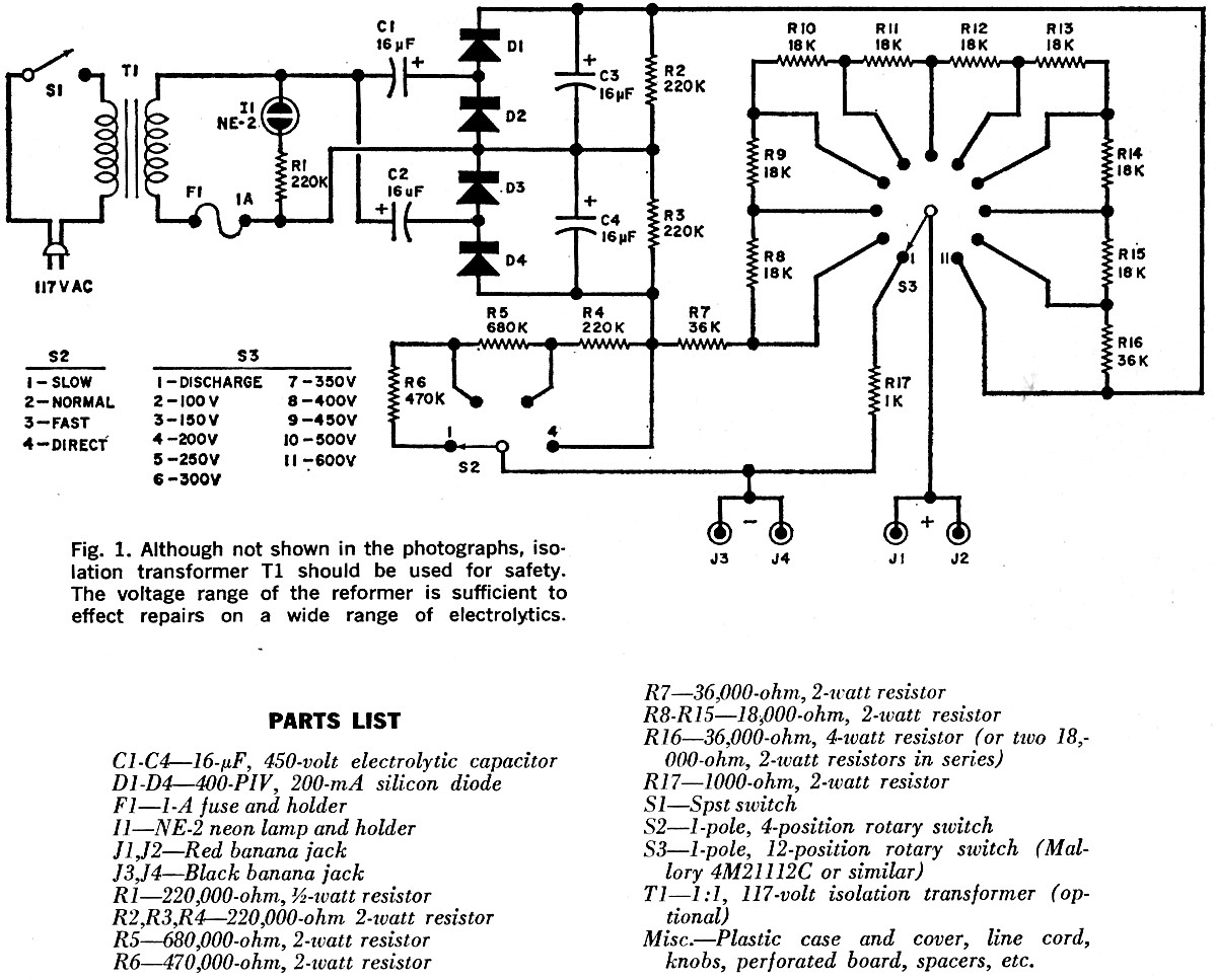
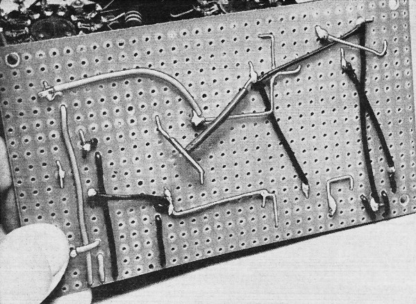
Fig. 1 - Although not shown in the photographs, isolation transformer T1 should be used for safety. The voltage range of the reformer is sufficient to effect repairs on a wide range of electrolytics.
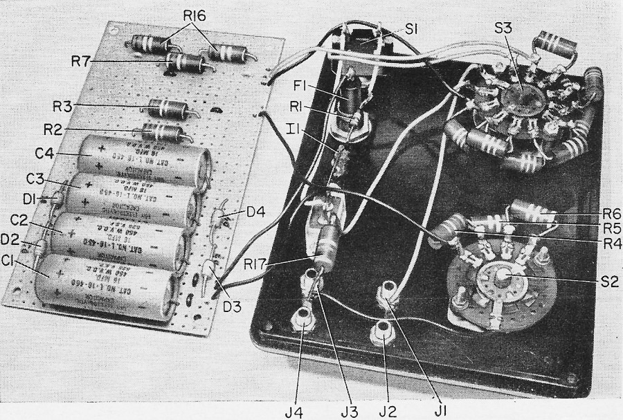
Perf board construction may be used with the operating controls and jacks mounted on the front panel of the selected cabinet. A TV-type "cheater" connector is used to make the power connection. Mount the perf board on suitable spacers and be sure that components on the board do not make electrical contact with any of the front-panel elements.
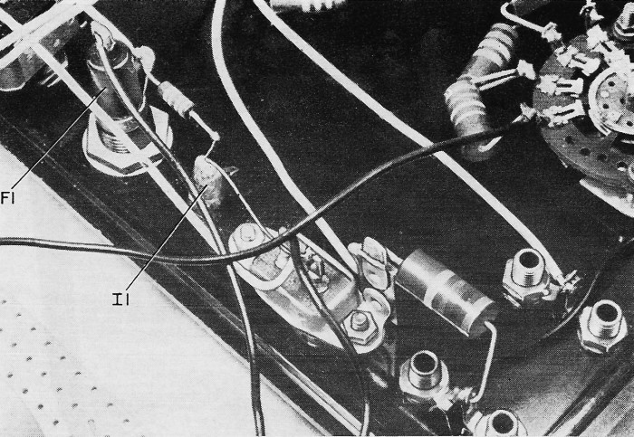
Be careful when drilling the holes in the plastic front panel as it will chip easily. The neon indicator lamp is cemented in the hole, other components use hardware.
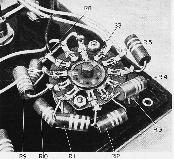
Insulated wiring is used to make interconnections. If a metal case is used, make sure spacers keep connections from touching the case. However, before finding out how to restore an electrolytic, let's be sure we know the exact nature of the trouble. What Is an Electrolytic Capacitor? An electrolytic capacitor usually consists of two flexible sheets of aluminum foil separated by gauze impregnated with an electrolyte. Leads are connected to each foil section. The foil connected to the positive lead has an oxide coating which serves as the capacitor's dielectric. It is the thickness of this coating that determines the working voltage of the capacitor. While the capacitor is being used, the oxide coating is preserved by chemical processes resulting from the voltage impressed across the terminals. Unfortunately, when it is in storage, time and ambient heat take their toll and the oxide deteriorates. When the full working voltage is applied to a capacitor whose oxide is weak, the latter breaks down and a short circuit is placed across the circuit. Reforming the Dielectric. The dielectric of a suspect capacitor can be reformed by connecting a low dc voltage across the capacitor and slowly increasing the voltage until the rated value is reached. This must be done over a long period of time to allow the oxide to reform properly. The "Electrolytic Restorer" described here does this job automatically, and requires only an occasional look at a dc voltmeter to check progress. The cost of the project is about $14 if all parts are bought new. Construction. The prototype shown in the photos was housed in a conventional plastic case although any type of arrangement will suffice. The schematic of the circuit is shown in Fig. 1. Exact placement of parts is not given since dimensions are not critical and the control locations can be changed depending on personal preferences. Most of the circuit can be assembled on perforated board. The front panel controls and jacks are mounted directly on the case cover, making sure that an leads are long enough to reach the electronics board. For safety, a 1:1 ac line isolation transformer should be used, though this is not shown in the prototype. Operation. The electrolytic capacitor to be reformed is connected to the output jacks, making sure that the polarities are observed. The positive side of the capacitor is connected to either J1 or J2 and the negative side to either J3 or J4. The dc voltmeter for checking the reforming action is connected to the remaining two jacks. Make sure that the polarity and voltage range are correct. The voltmeter can be disconnected and reconnected at any time without affecting the operation. Place S3 in the Discharge position, ping the unit in, and turn on the power. Neon indicator lamp I1 should glow. Set the desired forming rate on S2 and then rotate S3 to the working voltage of the capacitor. If the capacitor is unformed, the voltmeter will indicate a much lower voltage than that set on S3. Note that the voltmeter indication starts to increase quickly at first, then slows down as the dielectric forms. The rate of increase is determined by the condition of the capacitor and the setting of S2. When the Slow setting is used, the operation takes longer but the oxide formed will be of better quality The opposite is true for the Fast setting. Use the Normal position for most cases. When the voltage across the capacitor is approximately equal to the set on S3, put the switch on Discharge and remove the capacitor. No harm will be done if the capacitor is left connected longer than required, so it is not necessary to check progress constantly. To use the unit as a high-voltage, low-current power supply, set the forming rate switch (S2) to Direct. A current of 4 mA may be drawn continuously, and somewhat higher currents for a short period of time. (A load current of 10 mA causes a dissipation of 3 watts in the divider resistors.) The Electrolytic Restorer can also be used for a quick go-no-go check of voltmeters. Comparison of voltage switch settings and voltmeter readings will reveal any gross inaccuracies. Theory of Circuit Design Diodes D1 through D4 and capacitors C1 through C4 form a half-wave voltage quadrupler rectifier with a dc output of approximately 600 volts. Resistors R7 through R16 form a voltage divider network and S3 selects the desired voltage and applies it to the parallel-connected positive output jacks J1 and J2. The negative side of the power supply is connected through a switch-selected resistor network consisting of R4 through R6 to the parallel-connected negative jacks J3 and J4. The use of S2 determines the forming rate, The Direct position permits the unit to be used as a high-voltage, low-current power supply. This position can be eliminated if desired. The Discharge position of W3 places R17 across the output to discharge the formed capacitor, while resistors R2 and R3 keep a small load on the power supply and discharge the power supply capacitors. During the forming process, the capacitor's resistance is low so most of the voltage is dropped across the limiting resistor. As the oxide coating in the capacitor is re-formed, less current flows through the capacitor, causing the voltage across it to increase. When this voltage equals the preset voltage on S3, the reformation is complete.
The finished front panel should be labeled as shown here. A coating of transparent plastic spray keeps lettering from becoming smeared.
Posted January 22, 2024 |
|