September 1960 Popular Electronics
 Table
of Contents Table
of Contents
Wax nostalgic about and learn from the history of early electronics. See articles
from
Popular Electronics,
published October 1954 - April 1985. All copyrights are hereby acknowledged.
|
There is little incentive
to build your own field strength meter these days when commercial instruments are
readily available and relatively inexpensive. For instance, you can buy an
MJF-801 FSM with a 100 kHz to 500 MHz spectrum
coverage for
just $45, brand new. More sophisticated, calibrated instruments are available for
a lot more, but this basic unit is dirt cheap. However, if you want to read a little
about the theory behind a field strength meter and see how one goes together, this
article from a 1960 issue of Popular Electronics magazine provides that
opportunity.
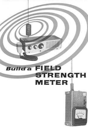
Build a Field Strength Meter
By Russell Keller, K9CZO
Are you curious about the radiation pattern of your CB or ham antenna? Here's
a simple field strength meter (FSM) that will give you an indication of relative
field strength on either the 6- or 10-meter ham bands or the 11-meter Citizens Band.
This little instrument is nothing more than a tiny receiver which drives a meter
instead of headphones. The meter lets you read the relative signal strength of your
signal at various points near your transmitting antenna. Parts should cost less
than $10, and total construction time shouldn't exceed a few hours.
Construction
The unit should be housed in a 4 1/4" x 2 1/4" x 1 1/2" (or larger) metal box;
unshielded plastic boxes are not suitable since inductive pickup by the FSM's coil
will give a false meter reading. Mount the r.f. portion of the FSM (capacitors C1
and C2, coil L1, jack J1, and diode D1) in the upper half of the box as shown. Insulate
antenna jack J1 from the box with a fiber washer. Keep all leads in the r.f. portion
short, and use a heat sink when soldering diode D1 and transistor Q1.
A one- or three-band version of the FSM is possible, the only difference being
in the choice of tuning capacitor C1. For a three-band model (the 6- and 10-meter
ham bands and the Citizens Band), use a 75-uuf. unit (Hammarlund APC-75 or equivalent)
for C1. If you want only a six-meter FSM, use a 25-uuf. unit (Hammarlund APC-25
or equivalent).
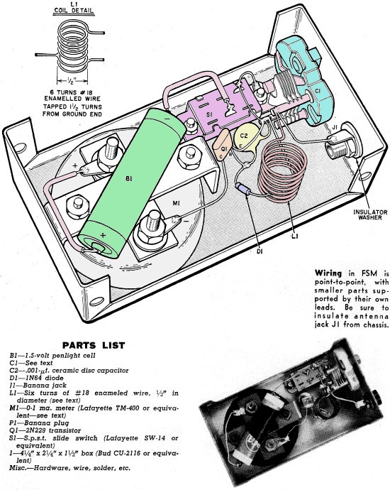
Coil L1 consists of six turns of No. 18 enameled wire, 1/2" in diameter. Solder
L1 directly across the terminals of capacitor C1 and solder the negative lead of
diode D1 to a tap 1 1/2 turns from the ground end of L1. Be sure to scrape the enamel
from L1 in the area of the tap before soldering D1 in place. All other components
except meter M1 are also soldered in place by their leads.

Wiring in Field Strength Meter is point-to-point, with smaller
parts supported by their own leads. Be sure to insulate antenna jack J1 from chassis.
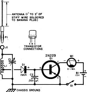
Schematic diagram of field strength meter. Exact values of C1
and M1 will depend on desired range and sensitivity of unit; switch S1 can be omitted
if antenna is unplugged whenever meter is not in use.
A battery holder is not used since zero-signal current drain is only a few microamperes
and penlight cell B1 should last indefinitely. On-off switch B1 can also be dispensed
with if desired, but the antenna should be unplugged when the FSM is not in use.
Mount meter Ml in the lower half of the box. For a more sensitive instrument,
use a 500-ua. or 100-ua. meter instead of the 1-ma. unit specified; no circuit changes
are needed for either of these meters. With one of the more sensitive meters in
the circuit, you can operate the FSM with a shorter antenna and measure r.f. field
strength at a greater distance from the transmitter.
Make a short whip antenna, as shown, by soldering a 1' or 2' length of No. 12
or No. 14 busbar to a banana plug. Jack J1 on the FSM is a banana jack and permits
the antenna to be unplugged when the FSM is not in use.
Operation
You can use the FSM to check the radiation pattern around your antenna or to
see if your transmitter is improperly shielded and radiating r.f. Before these checks
can be made, however, the FSM must be tuned to the transmitter. Do this by inserting
the FSM's whip antenna into J1 and placing it near the transmitter. Then rig a temporary
short-wire antenna to the transmitter, and tune up the transmitter. If yours is
a CB rig, just switch to "transmit" and use a clear channel. In any case, keep all
experiments down to a minimum so that already burdened Citizens Band and ham frequencies
are free of unnecessary interference.
Switch on the FSM and adjust capacitor C1 to the transmitter frequency. The meter
will show a sharp rise from the zero mark at the transmitter's frequency. Adjust
C1 for a maximum reading on the FSM. If the meter goes off scale, move the FSM further
away from the transmitting antenna. At this point, you'll notice that the FSM pickup
depends on its polarization with the transmitting antenna: maximum pickup results
when the FSM antenna and the transmitting antenna are parallel to each other.
Once the FSM is tuned to the transmitter, disconnect the temporary antenna and
connect your regular transmitting antenna. If your transmitter and coaxial transmission
line are properly shielded and grounded, you should get no reading on the FSM no
matter how close to the transmitter or coax the FSM antenna is placed.
When this check has been made, go outside to your transmitting antenna and turn
the FSM until its antenna parallels the transmitter's. Walk around the transmitting
antenna with the FSM, taking care to stay at least several wavelengths away from
the antenna.
The r.f. field you detect should correspond with the type of antenna you have.
If your antenna is directional, the r.f. field will be stronger in one location
than in another; this is true of horizontal antennas. Vertical antennas, on the
other hand, should exhibit a perfectly uniform field in a 360 degree sweep. Antennas
with reflectors should be most effective on the side away from the reflector.
How It Works
Operation of the FSM is similar to that of a receiver using a diode detector
followed by a one-transistor amplifier. In this case, the transistor feeds a milliammeter
rather than headphones. When r.f. is picked up by the antenna, it is tuned by coil
L1 and variable capacitor C1 . Diode D1, connected to a low-impedance tap on L1,
rectifies the r.f. appearing across the L1-C1 tuned circuit. The rectified signal
is filtered by capacitor C2 and fed to the base of transistor Q1, where it is amplified
and fed to meter M1. Serving as a visual indicator, Ml measures the amplitude of
the rectified signal, which is proportional to the r.f. field strength. Battery
B1 powers Q1 through on-off switch S1.
Posted August 17, 2021
(updated from original post on 3/26/2013)
|