|
July 1965 Popular Electronics
 Table of Contents Table of Contents
Wax nostalgic about and learn from the history of early electronics. See articles
from
Popular Electronics,
published October 1954 - April 1985. All copyrights are hereby acknowledged.
|
 In today's lingo, this 1965 Popular
Electronics magazine project might be considered
a cross between the Steampunk and the
Maker realms.
It is more than just a desktop conversation piece - although it would be a very
fitting fixture - in that the "Milliwatter" Morse code transceiver is fully functional,
portable (with it's steam engine power source) radio. All the parts needed to build
your own model - miniature working steam engine, DC generator (aka a DC motor),
code keyer, and electronic components - are still available. It appears you can
build a bare-bones version for under $100, or go all out with vintage-looking components
for about $300-$400. If you undertake this project, I'll be glad to post a photo
of your masterpiece here. In today's lingo, this 1965 Popular
Electronics magazine project might be considered
a cross between the Steampunk and the
Maker realms.
It is more than just a desktop conversation piece - although it would be a very
fitting fixture - in that the "Milliwatter" Morse code transceiver is fully functional,
portable (with it's steam engine power source) radio. All the parts needed to build
your own model - miniature working steam engine, DC generator (aka a DC motor),
code keyer, and electronic components - are still available. It appears you can
build a bare-bones version for under $100, or go all out with vintage-looking components
for about $300-$400. If you undertake this project, I'll be glad to post a photo
of your masterpiece here.
Build a Steam Powered Ham Rig
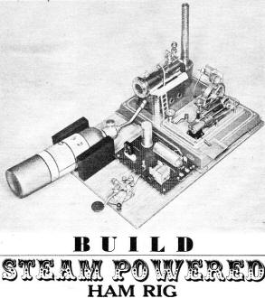
Single-transistor flea-power "Milliwatter" transmits readable
c.w. signals over a distance of three miles without a battery.
By Harland B. Smith, W8VVD
Since James Watt first patented his steam engine back in 1769, man has found
many uses for this source of power. But perhaps the most unusual one of all) in
this day and age anyway, is to harness it to a ham rig such as the "Milliwatter."
Taking its power from a steam-driven generator, the Milliwatter will put out
between 10 and 15 milliwatts, easily providing readable signals at distances greater
than three miles. So whether you would like to try your hand at flea-power operation,
need an emergency transmitter that can run without a battery, or are looking for
a Science Fair project, this gadget is for you.
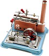
Steam Engine. Obtaining a steam engine for this project should
present no difficulty since many mail order houses carry such items. Although most
model steam engines will provide adequate power to drive a generator, select an
engine with a fairly large boiler to eliminate repeated refilling and time wasted
waiting for a new head of steam to build up. The engine and the other components
can be mounted on a heavily varnished 12" x 18" x 1/4" plywood board.
The steam engine can be fired by anything from a candle to a propane gas tank.
Although most companies recommend using dry fuel tablets, you will find a propane
tank more convenient. Use wood screws to hold a 3" x 4" x 1" wooden block on each
side of the propane tank to prevent it from rolling around.
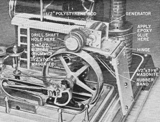
Fig. 1. Grommet fitted over polystyrene rod serves as a
drive shaft to couple generator to the steam engine's flywheel. Hinge-like generator
mount under rubber-band tension allows drive shaft to "follow" the flywheel. Engine
speed can be varied to control generator output.
Since the normal position of the control valve on the tank nozzle will inconveniently
face down when the nozzle points up, loosen the compression nut at the base of the
nozzle pipe and rotate the pipe until the nozzle points in the same direction as
the valve. The valve will now be easy to get to and will serve as a handy vernier-like
control of engine speed.
Generator. Although any small permanent magnet motor, such as
one that can be salvaged from a battery-operated toy, will function as a generator,
the motor described in the Parts List with its 3.2 to 1 gear train is recommended.
It produces the desired output voltage at a reasonable armature speed. A "spring-loaded"
drive mechanism couples the generator to the engine. As shown in Fig. 1, a
rubber-tired drive shaft attached to the generator rides on the steam engine's flywheel.
A suitable drive shaft and tire can be made from a 5/8" length of a 1/2"-round
polystyrene or wood dowel and a grommet having a hole diameter of 7/16" and an outside
diameter of 3/4". A smaller grommet might load the engine excessively and a larger
one would make it necessary to run the engine at a higher speed. Drill a hole in
the center of the dowel, just large enough to allow a press-fit over the end of
the axle holding the larger gear on the generator. Then stretch-fit the grommet
over the newly made drive shaft.
The generator is mounted on a 1 1/2" x 1 3/4" piece of 1/8" Masonite board hinged
to another piece of 1 1/2" x 3 1/8" X 1/8" Masonite. The second piece of Masonite
is screwed to the base of the steam engine as shown in Fig. 1. Use epoxy cement
to hold the generator to the first piece of Masonite. Connect a rubber band or spring
between the two hinged sections of the support to provide pressure between the flywheel
and the drive shaft. Too much tension can overload the engine. Too little will permit
slippage.

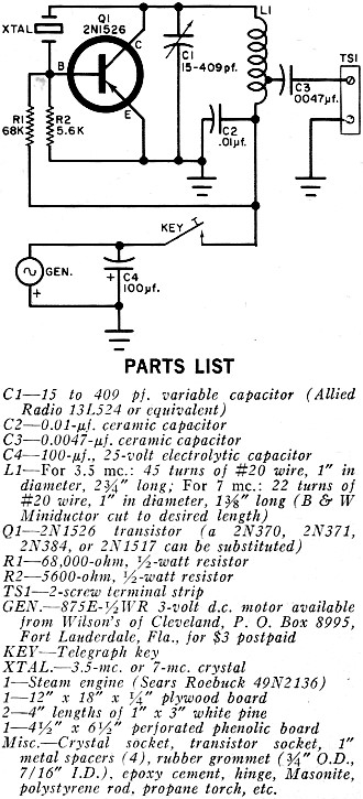
Fig. 2. Coil and crystal can be changed to work different
ham bands. A 3-volt battery can be used to operate and test the transmitter; the
trick is to operate under a head of steam.
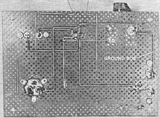
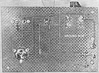
Fig. 3. Bottom view of transmitter circuit board shows how
to interconnect components. Allow some air space between crossed wires.
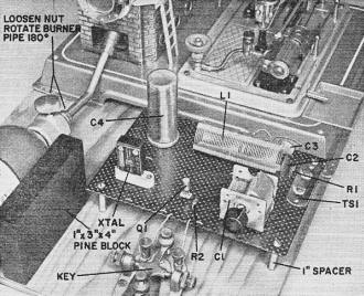
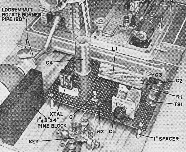
Fig. 4. The entire project is mounted on a plywood board
which measures only 12" x 18". Burner pipe is rotated at the compression fitting
to enable the gas control valve to face up, making it easier to handle. The gas
can be turned down to conserve steam when the transmitter is not used.
Transmitter. Consisting of a single-transistor crystal-controlled
oscillator (Fig. 2), the transmitter is simple and straightforward. Transistor
Q1 is connected in a grounded-emitter, double-tuned configuration and operates in
much the same manner as a tube in a tuned-plate, tuned-grid oscillator circuit.
The crystal, besides determining the frequency of the oscillator, also supplies
the feedback needed to sustain oscillation. Depending on the crystal, and the coil
(L1), you can operate on 40 or 80 meters. Keying is accomplished simply by interrupting
the series-fed power supply. A 4 1/2" x 6 1/2" perforated board holds all of the
transmitter components.
Before starting the engine for the first time, spin the flywheel by hand in the
same direction that it will turn when steam-driven and check the polarity of the
voltage across C4 with a d.c. voltmeter. If the polarity is not correct, reverse
the two leads from the generator.
Almost any long wire connected to the rig will suffice as an antenna. However,
best results can be obtained from a dipole cut to the operating frequency.
Testing and Use. In testing the transmitter, you may find it
easier to work with a 3-volt battery than with the generator. Disconnect the key
from the generator and C4, and connect the battery between the key and ground bus.
Depress the key and tune C1 until you hear the transmitted signal in a nearby receiver.
Next, vary the tap position on L1 and tune C1 until you radiate the strongest
signal while still allowing the crystal to start reliably each time the key is depressed.
You may have to detune C1 slightly to get the crystal to start. When you are satisfied
with the results, remove the battery and reconnect the generator and C4.
Now it's time to fire up the engine. After building up a head of steam, set the
engine speed so that approximately 3 volts appear across C4 with the key open. The
transmitter input will be between 10 and 15 milliwatts. The engine can be made to
deliver up to 5 or 6 volts, but at the expense of more steam and higher fuel costs.
Remember, the Milliwatter works in the ham bands. You must possess an amateur
license before you put the unit on the air.
Posted June 24, 2024
(updated from original post on 6/6/2018)
|