|
August 1970 Popular Electronics
 Table
of Contents Table
of Contents
Wax nostalgic about and learn from the history of early electronics. See articles
from
Popular Electronics,
published October 1954 - April 1985. All copyrights are hereby acknowledged.
|
You have probably seen some
pretty atrocious coaxial cable connector installations. You might have even been
responsible for a few of them ;-( It could be tempting, at least for frequencies in
the lower megahertz range, to allow yourself to be a little sloppy with coaxial
cable preparation and connector attachment, but doing so can result in marginal
functionality if power levels are high or if power levels are extremely low. When voltage
levels are high, excessive air gaps between the inner and outer conductors can result
in arcs, and poor connections can generate intermodulation products high enough
to cause interference (possibly subjecting you to a violation citation from the
FCC). At very low power levels, distortions and lack of symmetry in the interface
between the cable and the connector can result in high loss and a high voltage standing
wave ratio (VSWR), which might result in lower received power and accompanying lower
signal-to-noise ratio (SNR).
Care and Handling of Coaxial Connectors the Quick, Foolproof Way
By William I. Orr, W6SAI
Many of the so-called UHF connectors were developed during World War II for use
with medium size coaxial r.f. cables (such as RG-8/U and RG-11/U). Now generally
supplanted by the newer Series N connectors in commercial equipment, these inexpensive
and readily available UHF connectors are still widely used on amateur, CB, and SWL
equipment. The most common members of this family are the male plugs (PL-259, PL-259A,
and UG-295/U) and the female receptacles (SO-239, UG-296/U).
The male plug, a beguilingly simple affair, has a non-constant impedance, is
a non-waterproof device and (to many exasperated amateurs and CB'ers) is an invention
of the devil. A look at the PL-259 plug shows instantly how it should fit on the
end of a piece of coax cable; the installation is self-evident! But, alas, getting
the plug properly astride the cable end and soldered firmly in place is a frustrating
and time-consuming task. In too many instances, the user simply gives up the battle,
jams the connector on the end of the cable, and solders what he can, leaving whiskers
of copper braid ready to short out the plug.
UHF Connectors
For RG-8A/U and RG-58/U Cable Plugs:
PL-259, PL-259A, UG-295/U Adapters for RG-58/U: UG-175/U, UG-410/U Right-angle
adapter: UG-297/U, UG-646/U, M-359 Adapter, straight (female-female): PL-258,
UG-360/U, UG-299/U Receptacle: S0-239, UG-296/U Adapter, straight (male-male):
Dow-Key F-2 Hybrid adapters: UHF (female) to BNC (male): UG-255/U UHF
(male) to BNC (female): UG-273/U UHF (female) to N (male): UG-146A/U UHF
(male) to N (female): UG-83B/U UHF (female) to male phono connector: Dow-Key
A-210 UHF (male) to male phono connector: Dow-Key A-211 UHF plug (solderless):
Amphenol 83-851 (for RG-8A/U)
True, the plug manufacturers provide nifty little drawings showing how the plug
should be placed on the cable; but these pieces of advertising art merely make the
frustrating experience seem more bitter, since sooner or later most amateurs come
to the reluctant conclusion that the PL-259 plug was never intended to be placed
on a coaxial cable by the hand of man!
I have battled the PL-259 plug problem for longer than I care to admit and I
finally solved the dilemma by switching to the newer and better type N coaxial fittings,
which were seemingly designed by a sane mind. However, time does not march on, and
a large amount of gear in the W6SAI station is equipped with the PL-259's matching
partner, the ubiquitous SO-239.
Finally, with the assistance of W6CYL, who had made his peace with the coaxial
plug problem, it was decided to try a system approach that would solve the PL-259
question once and for all. Here is the solution.
Coaxial Connector Assembly
The mating cable must be properly prepared if the
connector is expected to operate to its fullest capability. With a little care and
some inexpensive tools, a well-engineered assembly may be made in a few minutes.
In addition to a soldering iron or gun, you will need: a ruler, a sharp knife (the
Stanley 99A Shop Knife is recommended), and a tubing cutter (the General Hardware
#123 Midget Tubing Cutter is recommended). Oh yes, you'll need a pair of wire cutters
to snip the cable to proper length, also.
Follow this procedure carefully:
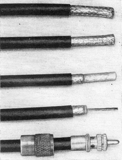
By the time you have finished step 4, the end of your RG-8A/U
cable should look like this.

Photo shows, from top to bottom, the results of steps in preparing
the cable.
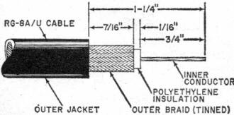
Step 1. Slide the coupling ring of the PL-259 over the coaxial line. Next, take
the shop knife and circumscribe a cut in the outer, black jacket of the cable about
1 1/2" back from the end. Make the cut at right angles to the cable so that the
end of the vinyl jacket will be square and ship-shape. Slit the free end of the
jacket with the knife and peel it off.
Step 2. You now have part of the outer braided shield exposed. Using a hot soldering
iron or gun, quickly and smoothly tin the braid, making the shield a solid entity.
Do this quickly so as not to unduly overheat the inner polyethylene insulation of
the cable. If you take too long, the inner insulation will melt and "squirt" out
between the interstices of the braid. Don't worry; you'll obtain expertise in soldering
the braid once you set your hand to it. Clean the left-over flux from the braid
with paint thinner after the solder cools.
Step 3. Next, cut the soldered braid with the tubing cutter. You'll want to cut
it so that 7/16" is left exposed. Using a soft pencil, make a mark on the braid
exactly 7/16" out from the black jacket. Place the tubing cutter over the braid
so that the cutter wheel falls on the pencil mark. Tighten the cutter a bit and
slowly revolve it about the cable. Tighten the cutter wheel once or twice again
and continue to revolve the cutter. Four or five revolutions, and the tubing cutter
will neatly slice the solid braid. The unwanted braid end may be easily pulled off,
using the wire cutters as snips.
Step 4. Trim the inner polyethylene insulation
of the cable. It should be cut cleanly (using the utility knife) so that a collar
about 1/16" wide is left at the end of the outer braid which was just trimmed. Go
slowly, so that you do not nick the inner conductor. Once the slug of insulation
is free, it may be removed from the cable by grasping it with your fingers and slowly
but firmly pulling and rotating it at the same time. When the slug is off, tin the
inner conductor.
Step 5. You have now come to the moment of truth. The cable is ready for the
PL-259 shell. It should be pushed on the cable end and rotated with the fingers
so that the internal threads of the shell are screwed onto the outer vinyl jacket
of the cable. As the plug is screwed onto the cable, you should see the tinned outer
jacket appear through the four solder holes of the plug. Continue twisting the plug
onto the cable until the braid is completely visible through all holes.
Step 6. The last step is to solder the braid through the solder holes of the
plug and solder the center conductor to the center terminal of the plug. Use an
iron or gun with a small point and make neat connections to the braid, taking care
that the solder does not run over the outer threads of the plug. With a little care,
you'll have a work of art. When the joints cool, examine your masterpiece and then
slide the coupling ring down over the plug.
Sealing for Outdoor Use
The PL-259 is not waterproof and must be protected against
moisture by an additional covering. If water does get into the plug, it can be very
quickly sucked down the coaxial cable by capillary action. Soon the entire outer
braid becomes corroded and line loss rises rapidly.
To seal the plug and line properly, the mating surface between the plug and the
matching SO-239 receptacle should be packed with silicone grease. The connectors
are then mated and the excess grease is forced out of the joint and wiped off. The
next step is to wrap the coaxial joint thoroughly with pressure sensitive vinyl
electrical tape. Several layers of tape should be used; and the wrappings should
extend beyond each connector a minimum of four inches, making the total wrap about
ten inches long. The tape should be put on under tension, with one layer overlapping
the one beneath. As a final precaution, the cable run should be dressed so that
water cannot run to a joint and stand there.
Use With Small Cables
The popular PL-259 UHF plug may be used with small-diameter
coaxial cables (such as RG-58/U and RG-59/U) by adding a reduction adapter. For
example, RG-58/U (52-ohm cable) requires a UG-175/U adapter and RG-59/U (72-ohm
cable) requires a UG-176/U adapter. Follow much the same procedure detailed above
with the exceptions noted below.
Step 1. Insert the cable end through the coupling ring and the adapter. Note
that the knurled end of the ring and the narrow end of the adapter face the open
end of the cable. Cut the end off 3/4" of the cable jacket with the utility knife.
Step 2. Fan the braid out slightly and fold it back over the outer jacket.
Step 3. Push the adapter forward under the braid and trim the braid with small,
sharp scissors to a length of 3/8". Next, using the utility knife, remove 5/8" of
the insulation from the center conductor. Be careful not to nick the conductor.
Tin the exposed conductor quickly with a small soldering iron.
Step 4. Carefully screw the plug assembly onto the adapter. The center conductor
will pass through the center pin and the braid should appear through the side holes
of the plug assembly. Using an iron with a small soldering tip, solder the braid
through the plug assembly holes. Use just enough heat to bond the braid to the shell.
After these have cooled, solder the center connector to the tip of the plug. Finally,
screw the coupling ring on the assembly.
Waterproofing and sealing are even more important when using either the RG-58/U
or RG-59/U cable.
Posted June 4, 2021
(updated from original post on 3/17/2014)
|