|
March 1972 Popular Electronics
 Table of Contents
Wax nostalgic about and learn from the history of early electronics. See articles
from
Popular Electronics,
published October 1954 - April 1985. All copyrights are hereby acknowledged.
|
Unless you happened to
live close to a television broadcasting tower, receiving an acceptable signal has
always been largely a matter of luck. Obstructions such as buildings and terrain can greatly
attenuate signal strength and multipath can generate telltale ghost images and confuse
the synchronization portions of signals. It was bad enough with black and white
(B&W) broadcasts, but the advent of color made the situation notably worse because
more information needed to be received properly in order to display a good picture.
Color TV adoption really began to take off in the late 1960s, and that is about
the same time when electronics and technology magazines started publishing articles
like this one about how to select a roof-mounted TV antenna. A follow-up article
appeared in the April 1973 issue of Popular Electronics. The
December 1958 issue had an antenna selection article as well,
obviously for B&W TVs.
Complete listing of recommended antennas for your viewing area
By Forest H. Belt
 Not too long ago, the only people who tried to
convince color-TV owners to buy rooftop antennas were the manufacturers of rooftop
antennas. Today, any TV salesman who assures you of a prime picture with only the
set's rabbit ears - well, he may disappoint you. Service technicians know; they
get many requests to fix a color-TV when the only problem is a weak or ghosty signal. Not too long ago, the only people who tried to
convince color-TV owners to buy rooftop antennas were the manufacturers of rooftop
antennas. Today, any TV salesman who assures you of a prime picture with only the
set's rabbit ears - well, he may disappoint you. Service technicians know; they
get many requests to fix a color-TV when the only problem is a weak or ghosty signal.
So don't disdain the antenna ads. Still, for the sake of snow-free and color-true
viewing, you should know what the ads try to say. Some play a numbers game, citing
how many decibels (dB) of gain (sensitivity) one antenna has over another. Some
ads tell of "front-to-back ratio," others of "side lobes" or some other equally
technical term. Catchy names abound, too: "Color Brite," "Color Guard," "Color Spectrum,"
"Color Tuned," "Magic Color," "Sensar," "Stellar 2001," and so on.
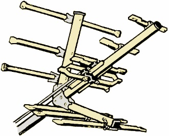
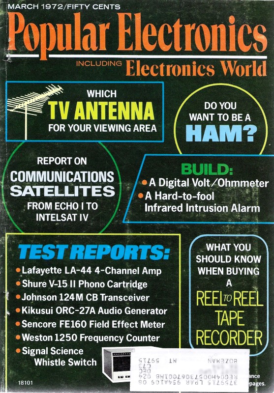
Fig. 1 - Winegard uhf section fits in front of other companies'
vhf units.
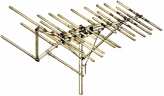
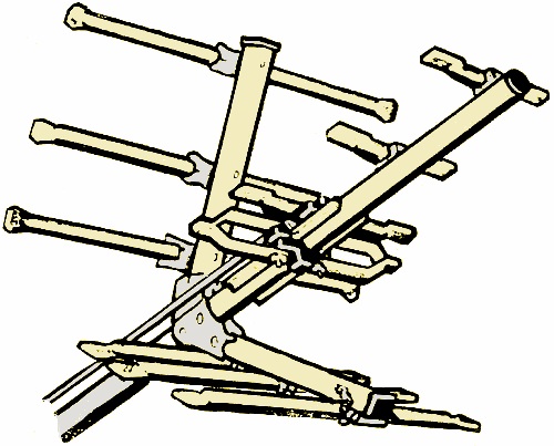
Fig. 2 - This antenna from Finco uses their frequency dependent
principle.
The important matter is what kind of picture the antenna puts on the screen of
your color receiver. That may depend on where you live. How far away are the stations
you watch? How powerful are they? Are they vhf or uhf? How high can you have your
outdoor antenna?
The accompanying full-page chart can guide your choice. Obviously, if you don't
watch any uhf stations, a vhf antenna is enough. Or, in a uhf-only area, you certainly
have no use for a vhf antenna. That is, you don't unless there's a not-too-distant
vhf station you can pick up with a high, sensitive antenna. In that case you might
consider a powerful all-channel model. And, if you're in a vhf-only or uhf-only
locality, ask around - a new station starting up soon might outmode your antenna.
Local, strong signals are usually received up to about 15 or 20 miles from the
transmitting antenna; medium signals up to 30 or 50 miles; and fringe signals out
to 70 or 100 miles. Vhf signals usually reach out somewhat farther than do uhf signals.
Terrain modifies the TV signal. If you find hills between you and the station, consider
a more sensitive antenna (from the next farther grouping). Likewise, if you live
near the "far" end of a mileage grouping, you may prefer the stronger antenna even
if the countryside is only mildly rolling. Beyond the mileages given above, even
the best antenna brings in only a snowy picture - unless the terrain is very flat
or you can put the antenna extremely high.
The chart lists the models suggested by major manufacturers for each signal category.
Don't go only by price. Ask your dealer or distributor to show you the antenna you
think best suits your requirements. Judge its sturdiness. Is it simple to put together
and raise into position? Check its weatherproofing. Consider directionality and
sensitivity (dB of gain). And, only then, compare prices.
Several popular antenna models are shown on these pages. Some have odd shapes;
but don't think those shapes are accidental. They are carefully thought out, for
very special reasons.
For All Channels. One example is a uhf design (Fig. 1)
patented by Winegard. What appears to be a folded dipole wrapped around the boom
forms the only active element. The lead-in is fastened to the opening at the bottom.
There's another gap at the top of the dipole - unlike ordinary folded dipoles which
are solid along the side opposite the feed-line. Two phasing bars (you can see only
one in the illustration), connected to the top gap, are just long enough at uhf
to act like zero impedance (a short circuit) across the gap.
This peculiarity permits tacking the whole uhf array, which Winegard calls a
"tetrapole collector," onto the front of a vhf antenna and using a single downlead.
At vhf, the phasing bars and the uhf dipole have no resonance. They act as mere
conductors tying the vhf antenna to the block where the lead-in fastens. Far station
signals in either uhf or vhf, the lead-in "sees" 300 ohms impedance.
Element Shapes and Spacing. Another patented design principle applies to the
Finco (Finney Co.) antenna in Fig. 2. The company tags the idea its "frequency-dependent
principle" (FDP). Short elements, the ones that pick up high-numbered channels,
are spaced far apart toward the front of the boom. This trick imparts higher gain
as the frequency goes up, which makes up for natural losses in the TV spectrum.

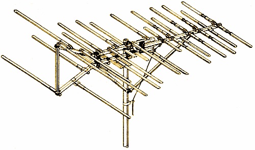
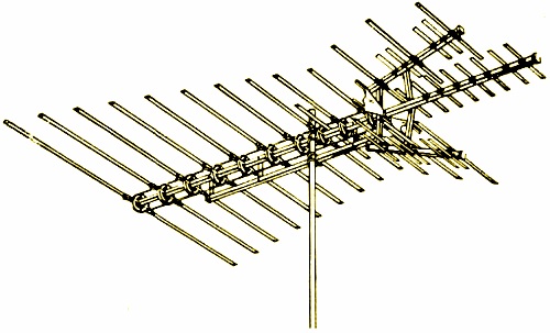
Fig. 3 - Log-periodic antenna by JFD.
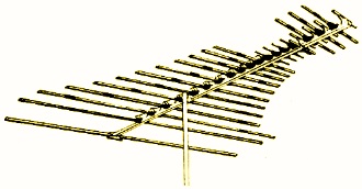
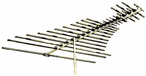
Fig. 4 - Element lengths follow exponential formula in GC
Audiotex design.
Another special feature narrows the front lobe of this antenna. Dipoles are not
straight across. Instead, they are staggered along two electrically separate booms.
Half of any given dipole is on one boom; its other half is further along on the
other. In effect, this transposes the phasing of the feed centers from dipole to
dipole. The twin lead-in connects directly to the ends of the two booms.
A design called the "delta reflector" adds a third feature to Finco's antenna.
Staggered mounting of elements continues on the delta-shaped boom that connects
at the back of the double boom. The delta array forms a closed resonant loop to
smooth response across the entire vhf band. The delta reflector is said to block
out signals from the rear more effectively than a straight reflector, improving
the front-to-back ratio.
Take a close look at the reflector elements up front, too. They are not solid.
Insulators divide them, to aid electrical breakup of longer elements so high-band
vhf "cells" form. The object, of course, is to improve performance on channels 7-12,
which is poor in some TV antennas.
Ordinary spacing, called "yagi spacing," places elements the same distance apart
along the antenna boom. Gavin sells antennas of this design. Element lengths vary
across the low vhf band, to spread the gain. As usual, the long elements operate
in thirds for high-band vhf. Responses off the sides, called "side lobes," necessitate
a slight forward-sweeping of reflectors - which also strengthens the front lobe
and raises gain. Short directors aid high-band gain.
Editor's Note: Over the past year, with only a few exceptions, outdoor TV antennas
have not changed much. However, the selection of an antenna, especially for color
TV, is important enough that we decided to update a chart of recommended antennas
which appeared almost a year ago in Electronics World. Major differences include
new model numbers and some price changes.
The Log-Periodic Idea. One design formula expresses a logarithmic
relationship between the velocity of TV signals and the size and spacing of antenna
elements. JFD Electronics pioneered this "log-periodic" principle. Gain goes up
as frequency rises, and impedance across the low and high spectrum stays smooth.
An all-channel log-periodic model is pictured in Fig. 3. Twin booms with
alternating half-dipoles accomplish feed transposition as already described, but
the halves of each dipole are directly opposite each other. Several forward elements
incorporate insulators. However, the JFD insulators are capacitive to "tune" the
elements for high-band resonance.
 Note that uhf array up front. Each set of
flat dipoles (there are two, mounted in wedge formation) is stamped from one metal
plate. Spacing and lengths of the dipoles follow the log-periodic formula, in the
uhf band. The tapered configuration, both vertical and horizontal, captures uhf
signals efficiently. Farther up front, the half-discs are broadband directors. JFD
calculates they deliver twice the gain of linear directors. Note that uhf array up front. Each set of
flat dipoles (there are two, mounted in wedge formation) is stamped from one metal
plate. Spacing and lengths of the dipoles follow the log-periodic formula, in the
uhf band. The tapered configuration, both vertical and horizontal, captures uhf
signals efficiently. Farther up front, the half-discs are broadband directors. JFD
calculates they deliver twice the gain of linear directors.
GC Electronics, under the Audiotex brand name, markets a line of antennas that
follow a different logarithmic formula. In Fig. 4, note the curved pattern
outlined by the element lengths. This special tapering, say designers, improves
broadband response. The dipoles are broken up by insulators, but not into thirds.
The short outer stubs make a few of the driven elements parasitic to others, smoothing
gain across the bands. You can't see them plainly, but small insulated wires transpose
the feed between each successive pair of elements.
Interestingly, the uhf array sandwiches in between the main vhf array and some
high-band vhf directors up front. Insulators break those directors up into parasitic
directors for the uhf band. This antenna thus has multiple use of elements to develop
higher gain at high band vhf and at uhf, yet keeping overall response smooth.
Multi-Feature Type. Fig. 5 exemplifies a high-gain all-channel
Jerrold Electronics Corp. model called the "VU-Finder." Elements are spaced Yagi-style.
Element lengths get shorter linearly from back to front. The feed harness is transposed,
but it is through the unique disc-shaped boom insulators which have imbedded conductors.
Every element is driven, with shorter elements acting as directors for longer ones,
and longer ones acting as reflectors for shorter ones.

Fig. 5 - Jerrold uses circular insulators.
Parasitic elements that appear to be part of the uhf array boost high-band vhf
gain too. A specially shaped bow-tie in the middle of the front array is the only
driven uhf element. Jerrold named the patented design of the bow-tie an "extended
resonance uhf dipole." The projections at each corner are angle-aluminum. The bow-tie
itself is not flat; it is molded with half-cylinder depressions toward the sides.
Two V-angled booms carry the uhf parasitic elements, forming a corner reflector.
To concentrate the front lobe and boost gain even further, another boomful of parasitic
directors extends out in front of the bow-tie.
Indoor/Outdoor. Two unusual antennas are the JFD Stellar 2001
and the Winegard Sensar. Both belong to a new breed of pre-amplified antennas designed
for either attic or rooftop installation.
Their amplifiers are solid-state and are part of the mast-mounted antenna. Coaxial
cable connects the antenna-and-amp unit to a power-supply distribution network at
the set. The manufacturers claim a performance radius of 40 to 70 miles, Keep in
mind, though, that very broadband devices such as these depend on fairly smooth
terrain for any real distance.
Which brings up another point. Despite the need for a really good signal for
acceptable color reception, you just might be situated where the signal is good
enough that you can get by with an indoor antenna. Try it, but don't be disappointed
if the unit that gives you a near-perfect black-and-white picture still doesn't
"cut it" for color.
Gavin makes an indoor model with two uhf loops, one slightly smaller for high
uhf channels. Some models have knobs to tune and orient the elements for ghost-free
reception. You may have to retune for each station.
JFD makes a complex indoor antenna. You can switch the elements as well as move
them around for various ghost conditions. The dipoles telescope, too, for best vhf
reception, and an inductive-capacitive circuit in the base lets you tune each station.
Channel Master sells an elaborate amplified indoor antenna called the "Chroma
1." The vhf dipoles telescope, while the uhf element is a trapezoid-shaped wire
loop, inside of which is a small trapezoidal metal plate. A coaxial cable from the
amplifier (in the base) feeds the signal to an impedance-matching uhf/vhf splitter
that connects to the TV set. Base controls rotate the uhf antenna, switch from uhf
to vhf, and tune the antenna-matching circuit for best performance on each station.
You take the first step to dependable color-TV reception when you recognize the
need for a really good antenna. The second step is figuring out what antenna is
"really good" for your house. The third step is to buy and install the antenna of
your choice.
Posted April 5, 2023
(updated from original post
on 11/12/2017)
|