|
July 1972 Popular Electronics
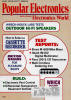 Table of Contents Table of Contents
Wax nostalgic about and learn from the history of early electronics. See articles
from
Popular Electronics,
published October 1954 - April 1985. All copyrights are hereby acknowledged.
|
Phased-locked loop (PLL) oscillator
circuits are the standard implementation for tunable frequency sources these days, as opposed
to LC tank circuits with either mechanical (variable capacitor and/or inductor) or electrical
(varactor) control elements. Crystal oscillators have been around for many decades, nearly
a century in fact, but it was not until the advent of PLL circuitry using solid state digital
ICs that such stability and accuracy was available across a wide range of frequencies. As
author Klaus Peter states, using a huge bank of fixed frequency crystals with selector switches,
even when using double and triple conversion schemes, is totally impractical from physical
implementation, production, and cost perspectives. These early PLL designs did not have the
convenience of single-IC circuits as are widely available today and at a very low price. The
plethora of USB-interfaced signal generators on the market now is testimony to that.
New Tuner Uses Single Crystal and Digital Frequency Synthesis
By Klaus J. Peter
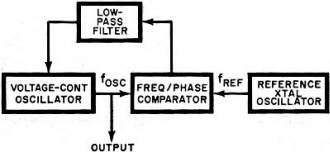
Fig. 1 - Simple phase-locked loop circuit locks oscillator to reference.
An ideal tuner must be sensitive and selective, have good spurious and image rejection,
have good capture ratio, and provide recovered audio with low distortion. Since low distortion
is achieved only when the r-f signal is properly tuned, low drift is essential to maintain
this condition. For operating convenience, a method of station pre-selection as well as the
ability to scan should also be available. The readout accuracy should be such that there is
absolutely no doubt as to which frequency or channel is being received. Manual fine tuning
to reach the center or low distortion point of a signal should be eliminated because mistuning
is probably the greatest source of distortion in FM reception.
The most obvious and simplest solution to eliminating fine tuning of the oscillator is
to use a crystal-controlled oscillator. Since the oscillator frequency is always 10.7 MHz
above the receiving frequency, 100 crystals covering from 98.8 MHz, to 118.6 MHz in 200-kHz
steps would be required for all channels. A 100-position rotary selector switch would serve
as a tuning knob and provide a mechanical or electrical readout determined by its shaft position.
This system effectively eliminates the need for fine tuning but is far too expensive since
the quartz crystals alone amount to about $200 in parts cost. Using frequency mixing techniques,
it is possible to bring the number of crystals down to 20 for dual conversion and 15 for triple
conversion but the additional switchable filter requirements also make this approach expensive.
Furthermore, multi-conversion designs may be troubled by spurious response and poor image
rejection performance due to the nonlinearity of the mixer circuits.
The Crystal Oscillator. The oscillator of the Scott 433 digital FM tuner
is crystal controlled on every frequency but uses only a single quartz crystal as a reference
standard. This is accomplished by making the oscillator part of a digital phase locked loop
(PLL) circuit. In order to understand this principle, let us look at the simplest PLL circuit
which locks an oscillator to a reference frequency.
When the system shown in Fig. 1 is first turned on, the voltage-controlled oscillator frequency
will not be exactly the same as the reference frequency. The output of the frequency-phase
comparator is an error voltage which tunes the VCO in a direction to minimize the error until
phase-lock condition is established and fosc = fref. Since the control
voltage for the VCO is ideally a dc voltage, the low-pass filter is used to remove any high
frequency components which might be present at the output of the comparator.

Scott 433 digital FM tuner circuitry is described in text by its designer.
In order to generate a large number of frequencies from a single reference, a programmable
divider is inserted into the PLL as shown in Fig. 2. The loop behaves as before except that
a submultiple of the VCO is now presented to the comparator and the frequency relationship
becomes
fosc / N= fref.
fosc = Nfref.
In North America, stations are assigned to fall on 100 channels from 88.1 to 107.9 inclusively
with a spacing of 200 kHz. Since the channel spacing requirement is 200 kHz, the reference
frequency of the crystal oscillator must be 200 kHz if its multiples are to fall on each FM
channel plus 10.7 MHz. Let us calculate what the divide ratio must be when the tuner is receiving
88.1 MHz or the bottom channel on the band.
The oscillator frequency will be
88.1 + 10.7 = 98.8 MHz
Substituting into the earlier equation to find the divide ratio N:
N = fosc = fref. = 98.8/0.2 = 494
This means that the voltage-controlled oscillator will be at a frequency of 200 kHz multiplied
by 494 or 98.8 MHz. The next channel higher at 88.3 MHz will require a divide ratio of 495
and so on until 107.9 MHz, the top of the band, is reached at a divide ratio of 593.
For the tuner to scan the entire FM band, the programmable divider must therefore be able
to divide from 495 to 593 inclusively.
Consequently every time a new station is desired, the divide ratio must be altered. Since
several IC counters are available with a variable modulo or programmable count sequence, one
of these is used here. The divide ratio is altered by inserting a binary code which affects
the length of the count sequence and hence the divide ratio. Each channel or frequency requires
a unique code which is presented to the divider.
The code itself is derived electronically and can be generated in a sequence which will
make the tuner appear to scan across the FM band. It actually "steps" across the band rather
than scans continuously since it only pauses (phase locks) on assigned channels. The tuner
can also be tuned or programmed by cards which present a binary code to the code generator
which in turn decodes it and passes it on to the programmable divider. The card system overrides
the other forms of sequential tuning and allows instantaneous pre-selection of stations by
using the. desired card.
Digital Frequency Readout. The tuner uses the familiar cold cathode neon
indicator tubes which were chosen for reliability, long life and reasonable cost. The display
is actuated by the same binary code which the code generator supplies to the programmable
divider to set its divide ratio. Aside from displaying the frequency in MHz which the tuner
is receiving at any given moment, the display serves as a self-checking feature for the code
generator as well as the card reader. The binary code from the code generator is decoded into
decimal form and used to drive the display; if an incorrect or non-allowable code is presented
to the divider such as one caused by a damaged card, the readout will immediately show the
error.
Fig. 2 - The programmable divider allows tuner to synthesize multiple frequencies.
The digital readout in the tuner is not simply hooked up to. a frequency counter which
counts the oscillator frequency minus 10.7 MHz. The frequency counter is a "passive" addition
which will work with any existing tuner while the PLL design is an "active" system which requires
an electronically tuned r-f section. In the passive system, manual fine tuning is still required.
With a PLL system the oscillator is forced to lock at each channel center, which always falls
exactly on the assigned frequencies of the broadcast stations.
The digital PLL system provides an r-f oscillator of crystal stability on all frequencies
plus an absolutely accurate digital display of the frequency being received. The binary code
generator setting the divide ratio allows the operator to scan the FM band manually at a preselected
speed or to let the circuit search for a station or stereo station automatically. If one station
of known frequency is desired, a pre-punched card can be used to tune to it immediately. This
feature will appeal to the discriminating music listener who has a small number of favorite
stations and selects definite programs. The scan feature on the other hand might appeal to
the less critical listener who usually scans the band until he hears something he likes.
Other Features. One of the extremely useful by-products of this system
is automatic interstation muting. The tuner just won't tune between channels. Noise muting
is also provided however for silencing empty channels; this type of muting is defeated by
a front panel switch. During the automatic "Stereo Station" scan mode, all mono stations are
muted. When tuning from one station to another regardless of which tuning mode is used, the
sound disappears without the usual transient swish or thump and reappears out of complete
silence again with the absence of annoying noise bursts and distortion.
All muting is done after the multiplex decoder by two FET series-gate switches which reduce
the signal by at least 60 dB in the muted condition without introducing a dc transient.
The r-f section in the tuner employs selected high-gain, low-noise FET's for both r-f gain
and mixer functions. A FET is also used for impedance matching and low noise in the first
stage of the i-f amplifier. Two 6-pole elliptical filters shape the passband of the i-f and
achieve a selectivity in excess of 70 dB which allows this tuner to select any one station
from a crowded area on the band.
The "Station" light on the front panel indicates the presence of a carrier and is actuated
by a zero-crossing detector coupled to the output of the ratio detector; the station light
is also a double check on the PLL and reference standard because it is actuated only if the
station is tuned to exact center. On noise which is present on empty channels, the station
light is extinguished automatically. The "Stereo" indicator will light up in the presence
of a 19-kHz subcarrier when the signal level is sufficient to give an acceptable signal-to-noise
ratio. A "Card Program" indicator shows at a glance whether or not card tuning is being used.
Aside from providing instantaneous pre-selection of station frequencies, the card serves as
a permanent memory since the code generator's volatile memory loses the station code when
power is turned off.
Trend to Complexity. The trend in consumer electronics is toward greater
circuit complexity made possible at low cost due to the use of integrated circuit technology.
The circuit designer gains flexibility in achieving performance goals and operating convenience
for the customer. Unless proper steps are taken, however, servicing of this type of equipment
can become a problem as troubleshooting time and test equipment expenditures increase drastically.
The best approach seems to center around modular construction with each module representing
a functional sub-assembly which can be replaced with no more effort than the vacuum tube in
an old TV set. Fault location is greatly simplified by the fact that each module performs
a definite function which can be monitored individually with a minimum of test instruments.
Once the faulty module is replaced by the service shop, it is sent back to the factory where
automated test facilities localize the fault to a component on the subassembly and it is either
repaired or scrapped. This module exchange policy has been used for some time and is gaining
in importance as equipment complexity increases. The customer also has the advantage of knowing
exactly how much the repair will cost if it is done after the warranty period has expired
because definite module exchange prices have been established. Even service shops with limited
facilities can repair a unit as complex as the digital FM tuner if a set of PC modules or
even another operating unit is available. Each module is simply in-terchanged with a new one
until the fault disappears.
Although the complexity of circuitry has increased, reliability has increased also. Through
the use of MSI (medium scale integration), the number of hard-wired interconnections has actually
decreased thus avoiding a significant number of failures. By screening TC's in incoming inspection,
testing assembled modules under worst case conditions before they are mounted into complete
units, and extensive life testing of finished products, the failure rate has been reduced
to a fraction of what it was a few years ago. The IC's used as building blocks in the digital
sections are of the standard variety already well proven in the computer industry and second
sourced widely.
Posted
|