|
March 1973 Popular Electronics
 Table of Contents Table of Contents
Wax nostalgic about and learn from the history of early electronics. See articles
from
Popular Electronics,
published October 1954 - April 1985. All copyrights are hereby acknowledged.
|
According to author R.R. Freeland,
manufacturing processes for radio-quality manmade crystals saw major improvements toward
the end of World War II. At the time, the process was highly manual-intensive, as
can be seen in this really nicely done 1940s video titled "Crystals Go to War."
Prior to the use of crystals as frequency-determining devices, inductor-capacitor (LC)
tank circuits were the dominant configuration. There were actually other frequency-determining
schemes like spark gaps and even vibrating mechanical reeds. As you might guess, anything
less than a crystal suffered from higher short-term and long-term stability, drift over
temperature, microphonics,
and the phase noise
- composed of multiple effects like shot noise, i/f noise, etc. - was relatively terrible.
Crystals for CB & Ham Communication
To Keep Your Signals Steady as a Rock, You Need Quartz Crystals in Proper Circuits
By R. R. Freeland
President, International Crystal Manufacturing Co.
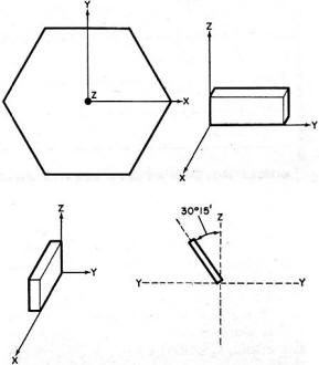
Fig. 1 - Axes for the mother quartz crystal. Both X-cut and Y-cut
blanks are shown. The AT-cut crystal is widely used.
Quartz crystalline material, natural and "grown" by man, has become the most widely
used device for controlling radio frequencies. Historically, crystal frequency control
began with radio amateurs back in the late 1920's. Full-scale production and use of crystals
in the commercial market began during World War II. Since 1945, however, considerable
effort has gone into improving crystal production methods and the circuits in which crystals
are used to provide close control over frequencies over wide temperature ranges.
Many crystals, particularly quartz, exhibit a property known as "piezoelectricity,"
whereby they convert mechanical energy into electrical vibrations (oscillations) and
vice-versa. A crystal blank cut from quartz will vibrate mechanically about one or more
nodal points when a voltage is applied to it. Both fundamental and harmonic (whole multiples
of the fundamental) oscillations are generated by the crystal.
The fundamental frequency at which a crystal is made to oscillate depends upon many
factors but mainly the crystal's size and thickness, the angle of "cut," and operating
temperature. As far as size and thickness are concerned, the smaller they are, the higher
will be the operating frequency. The cut of the crystal refers to the manner in which
the blank is sliced from the bulk crystal material, taking into account the six-sided
crystalline structure.
Of the general modes of oscillation obtainable from a crystal (extensional, shear,
and flexure), we are interested in only the shear mode for amateur radio and CB applications.
In this mode, wave propagation is parallel to the thickness dimension.
The thickness shear is sometimes called the high-frequency shear mode. The quartz
can also oscillate at a mechanical harmonic (must be an odd number) such that the two
opposite faces of the blank effectively move in opposite directions. The mechanical harmonic
should not be confused with the electrical harmonic which can be any multiple of the
fundamental frequency.

Fig. 2 - Edge-clamp or cemented-lead mount.
The orientation of the raw quartz crystal is universally defined by assigning X, Y,
and Z axes as shown in Fig. 1. The Z axis is commonly referred to as the "optical" axis
owing to the fact that it can be located by optical methods. No piezoelectric effects
are directly associated with it as they are with the X (electrical) and Y (mechanical)
axes. X-cut crystals are used mainly for low-frequency applications, and Y cuts are used
mainly for medium- and high-frequency applications. Hence, our only interest here is
in the various Y-cut crystals.
A simple Y-cut crystal is a poor frequency control device. So, the simple Y cut has
been replaced by rotated-Y cuts, the most common of which is the AT cut whose plane is
rotated around the X axis by approximately 35° from the Z axis. By carefully selecting
the angle of rotation, crystals with very small temperature coefficients can be fabricated.
For critical requirements, angle tolerances are maintained within 15 seconds of arc.
For less critical ham and CB applications, the tolerance can be within 3 minutes of arc.
The AT crystal is commonly mounted in its holder by the edge-clamp method (cemented
lead mount) as shown in Fig. 2. Plated electrodes cover part of the crystal face. Plating
on the opposite faces extends to the edges to provide good electrical contact. By keeping
the electrode area small, the capacitance is reduced and the principal activity is confined
to the central region of the crystal to improve stability. This, in turn, reduces the
impedance of the supporting wires.
High-quality piano wire supports the crystal. A small amount of conductive cement
assures a good connection between the wire and the plated electrode. (With the plated-wire
mounted crystal, calibration tolerances can be as high as 0.001 percent.) The crystal
is sealed in a vacuum or dry-nitrogen-filled glass or metal case.
Crystals are designed and processed to undergo a minimum of aging during their useful
lives. A 10-part-per-million rate the first year is not an unreasonable figure. The aging
rate decreases with time and usually levels off after about six months of operation.
Pre-aging by heat cycling can reduce the initial aging period.
When a crystal is put into operation, the lower the drive level, the longer its useful
life. The aging factors are more pronounced when a crystal is operated at high drive
levels, and the higher operating voltage increases the possibility of corona discharges
which, together with greater vibration amplitudes, can lead to crystal failure. To obtain
maximum life and stability, crystals should be operated at the lowest practicable drive
levels.
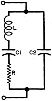
Fig. 3 - This is a simplified schematic of an equivalent circuit for
a typical quartz crystal mounted inside a holder.
Crystal Circuitry. The simplified equivalent circuit of a crystal
in its holder is illustrated in Fig. 3. Capacitor C2 represents the electrostatic capacitance
between the electrodes, while L, C1, and R represent the equivalent mass, compliance,
and frictional loss of the vibrating crystal. Capacitance C2 can be measured by conventional
methods; the series-resonant and anti-resonant impedances and frequencies can be measured
by using a crystal impedance meter. From these two sets of measurements, C1 and L can
be calculated. (The crystal can appear as either a low-impedance device at series resonance
or a high-impedance device at anti-resonance.)
Crystals can be operated at series resonance, but it is impractical to operate them
at exactly the anti-resonant frequency. Adjusted to operate at maximum voltage (parallel
resonance) at some proper phase and frequency, the crystal is most sensitive to frequency
changes with small changes in effective load impedance. Both the equivalent impedance
and resonant frequency change with effective load changes. A 30-to- 40-pF load operates
the crystal at a lower impedance point where small circuit changes have less effect and
the adjustment range is smaller with the same trimmer capacitor.
The total shunt capacitance across the crystal plays an important part in determining
the final frequency. However, the crystal itself bears the primary responsibility for
frequency stability, which is dependent upon the magnitude of the change in reactance
with frequency.
Crystal Performance. Crystals can be graded according to activity,
frequency stability, bandwidth, quality factor (Q), and parameter stability. Frequency
stability is the crystal's ability to minimize frequency changes arising from variations
in the parameters of the external circuit. Bandwidth is the useful operating frequency
range of the crystal. Quality factor is simply a figure of merit. Parameter stability
is the stability of the crystal parameters during changes in temperature, drive level,
and tuning adjustments. The stability of a crystal oscillator depends upon both the crystal
and the parameter stabilities.
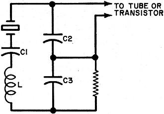
Fig. 4 - Typical crystal oscillator circuit.
Transmitter crystals are usually operated at the fundamental frequency into an approximate
32-pF load. A common crystal oscillator configuration is shown in Fig. 4. The maximum
effective load is present in this circuit when C1 is shorted. Inductor L is used to balance
out capacitive reactance to permit operating at series resonance.
Many CB rigs provide a single trimmer capacitor for all channels instead of individual
trimmers for each channel, which complicates correlation for many transmitters. Switch
lead lengths and dress, as well as component locations, affect the oscillator load capacitance.
Most of the CB transmitters that cover all 23 channels reduce the number of crystals
needed by combining several crystals to produce the desired frequencies and use the same
group for the receiver's oscillator. Two crystals must be considered for determining
the accuracy of the final signal frequency. Both crystals must track in tolerance over
the temperature range to yield the desired results. Not only does the crystal's temperature
characteristic become im-portant, but the exact oscillator load must also be known to
allow calibration.
Posted January 15, 2018
|