|
January 1968 Popular Electronics
 Table of Contents Table of Contents
Wax nostalgic about and learn from the history of early electronics. See articles
from
Popular Electronics,
published October 1954 - April 1985. All copyrights are hereby acknowledged.
|
While far from being an expert in the use of hand tools and small powered shop
tools, I have built enough
prototypes and models in my 61 years to have learned a fair
amount about what results in success and failure. Admittedly, there have been times
when quality has been sacrificed for the sake of cost and/or expediency. Personal
safety has sometimes been risked as well - usually for no real good reason. Luckily,
I still have ten fingers, two working eyes (although very near-sighted), and excellent
hearing. Surely, you possess none of my bad habits ;-)


This article from Popular Electronics magazine offers advice on how
to properly work with printed circuit boards (PCBs) and, indirectly, the enclosures
that might contain them. If you have never tired cutting a fiberglass PCB, you would
be surprised at how tough they are. I ruined a band saw blade one time when I was
too lazy to swap out the wood blade that was already on it for a metal cutting blade.
Standard steel drill bits do not last very long on them ,either. One handy bit (no
pun intended) of information I found here was the use of a
spur (aka pilot) point drill bit on plastic and
soft aluminum in order to reduce the wiggle that often results if the part is not
very securely clamped to the drill press table. It is because the two leading edges
of the drill bit try to cut into the material. Those same spur point bits are a
real potential hazard if the part is not clamped securely because they have a tendency
to violently wind the part up off the table and onto the bit shank, usually resulting
in it spinning on the bit. They scare me so much that I rarely use them on any type
of wood.
Brad point drill bit types cut a clean exit hole
and do not grab the material.
Cutting, Punching and Drilling of Printed Circuit Boards
Words of Advice from a Professional Toolmaker, so You Won't Botch the Job
By Alf Adel, W9CDB*

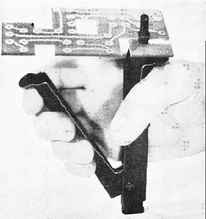
Fig. 1 - A nibbling tool trims, notches, or cuts up to 18-gauge
steel, 1/16" aluminum, and all types of plastic PC boards.
One of the biggest headaches for most electronic experimenters is the cutting
and drilling of printed circuit boards, or other similar sheet plastic materials.
Most PC boards are fabricated from a paper-base, thermosetting phenolic resin, making
them soft and brittle, and therefore susceptible to cracking and tearing unless
handled properly. However, such problems can be reduced, or even eliminated, by
the use of proper tools and techniques.
The following paragraphs will tell you what tools are best to use for cutting,
drilling, and punching PC boards, and which tools should not be used for these purposes.
Cutting
Sheet metal snips should never be used to cut PC boards. Their shear angle is
too great, and the use of this tool would only result in rough, ragged edges, and
possible damaging or cracking of the board.
Most sheet metal power shears will cut PC boards. However, any excessive angle
of the shear blade will rip the material along the cut edge. This happens because
the shear blade bends the material downward at the shear point, literally tearing
the two segments apart. If you want to use power shears, the cutting angle must
be corrected first. If this does not do the trick, try heating the PC board slightly
before attempting to shear it. Do not try to shear thermoplastics, such as polystyrene,
acrylics, etc., as they will always crack.
Although a saber saw, or hacksaw, is not recommended for cutting a PC board,
a metal-cutting band saw having at least 18 teeth per inch can be used. The copper
foil side of the PC board should be up during the cutting operation or the foil
may peel away from the base during the cutting.
Probably the best way to cut a printed board is with a nibbling tool. Nibbling
is a punch-and-die method of taking small "bites" out of the plastic, thus eliminating
the possibility of fracture (cracking) of the board while the punch takes the small
bites. This method, shown in Fig. 1, also prevents the copper foil from peeling
away from the phenolic base.
Drilling

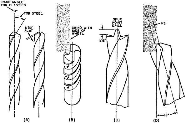
Fig. 2 - Drilling neat holes in plastic is simplified if you
modify some commonly used metal twist drills as shown here and explained in the
text. You can reduce the rake angle of a drill to zero by grinding a 1/32" flat
(a) across the cutting edge on both sides as shown in (b). A spur-point drill (c)
can be made from a conventional metal drill as shown in (d). These drills cannot
be used on metal once they are modified.
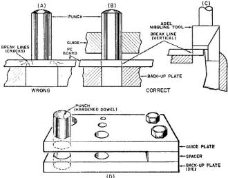
Fig. 3 - The wrong (a) and right (b) way to punch holes. Operation
of a nibbling tool is shown in (c). You can make your own punch plate assembly by
following layout in (d).
Using a conventional twist drill to make holes in any type of plastic material
(including PC boards) can be a problem. An ordinary twist drill is ground for cutting
metal and usually will dig in and rip through the bottom of the hole when you're
drilling through plastic. This is due to the rake angle at the cutting edge (lip)
of the drill. See Fig. 2(a).
You can modify a few twist drills for drilling plastics by flattening out the
rake angle. This will destroy the twist drill's usefulness for drilling metal, but
the advantage gained in clean drilling through plastic will more than compensate
for the investment of a few drills.
To flatten the rake angle, you'll need a high-speed grinding wheel. Clamp the
twist drill so that the cutting edge can be very carefully pushed in toward the
right-hand side of the grinding wheel as shown in Fig. 2(b). Grind a 1/32" flat
across the sharp cutting edge - in other words, reduce the rake angle from about
15 degrees to zero degrees (parallel to the long axis of the twist drill). Be sure
to flatten both cutting edges.
To drill holes in PC boards larger than 3/8", a spur-point twist drill is called
for. These drills are not too common, but you can modify an ordinary twist drill
to do the same job. Here, again, a high-speed grinding wheel is needed. In this
case, the tip of the ordinary twist drill will be cut away to create a spur-point
drill as shown in Fig. 2(c). You do this by clamping the twist drill at an angle
of about 15 degrees to the grinding wheel, with the cutting edge in line with the
horizontal axis of the wheel. See Fig. 2(d).
Hold the drill against the wheel and grind away the old cutting edge, except
for the one-third center part, to form a spur. Do the same thing on the other side
of the drill, making sure that the same amount is removed from each side of the
center. The center will extend about 1/16" above the spurs, and becomes the pilot
that will guide the drill. If the pilot is not exactly in the center of the drill,
gently grind the high side down using the side of the grinding wheel.
To sharpen this drill, hold it exactly in the same manner used to make it originally.
With the grinding wheel operating, rotate the drill clockwise about 30 degrees as
you gently grind. Start each grind with the cutting edge horizontal and lift upward
as you rotate. This will provide about 10 degrees of clearance at the rear of the
cutting edge and the pilot.
You now have an excellent sheet-metal drill. To make it useful for plastics,
grind a flat on the spurs as shown in Fig. 2(b).
Punching
Printed circuit boards can be cleanly punched by using a punch and a backup plate
with matching punch/plate-hole diameters. If the hole in the backup plate is larger
in diameter than the punch, many break lines, cracks, and splits will appear, as
shown in Fig. 3(a). When the punch and plate hole have the same diameter, the break
is clean and vertical through the material, the board will not crack, and a clean
slug of material the same size as the hole will be punched out. See Fig. 3(b). This
is the principle of the nibbling tool shown in Fig. 3(c).
A useful punch plate can be made as shown in Fig. 3(d). The lower plate acts
as a back-up plate (die) for the material. A spacer and a couple of nuts and bolts
secure the two plates together and keep them aligned. Drill various size holes through
the two plates to accommodate a variety of punch sizes.
When using a punch, keep the tool at least one punch diameter away from the edge
of the material.
Whenever cutting, drilling, or punching plastic materials, always use a sharp
cutting tool to reduce friction heating - one of the main causes of cracking and
tearing.
* Adel Tool Co., 4640 Ronald St., Chicago, Ill.
Posted September 4, 2019
|