|
December 1974 Popular Electronics
 Table of Contents Table of Contents
Wax nostalgic about and learn from the history of early electronics. See articles
from
Popular Electronics,
published October 1954 - April 1985. All copyrights are hereby acknowledged.
|
When this Digital
Filtering article appeared in a 1974 issue of Popular Electronics
magazine, the concept of switched capacitor filters (SCFs) was just entering the
realm of digital circuitry. One author, Carmen Parisi, credits none other than
James Clerk Maxwell for initially contriving the idea. Today, variations of
the switched capacitor filter are ubiquitously incorporated into integrated
circuits of all sorts, but at the time of this piece they were assembled from
discrete components including banks of capacitors, digital switches (counters),
and transistors. Figure 2 shows an experimental circuit that uses six capacitor
values for use at audio frequencies. The earliest IC switched capacitor filters
worked in the hundreds of Hertz realm, and gradually increased in frequency
until today they reach to around 100 kHz (see
Digi-Key SCF offerings).
New technique operates from a digital oscillator and uses no critical
elements
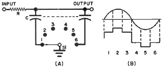
Fig. 1 - At (A) is a simple switch circuit which generates the
stepped waveform shown at (B) from a sine wave.
By Leslie Solomon, Technical Editor
Single frequency filters are important in a number of areas - RTTY, SSTV, radio
control, etc. There are two approaches that are usually used to accomplish such
filtering: either multi-element passive systems (which use precision components
and are somewhat bulky physically) or active filters (which use a few passive components
and an op amp). Even with the active filter, to obtain careful control of the selected
frequency, it is necessary to select precision passive elements.
Though either of the two approaches works well, there is a new filtering method
that is unique and should be of interest to the serious electronics experimenter.
Called digital filtering, the new method uses no critical elements and is "tuned"
with a digital oscillator. High-Q filters (even at low audio frequencies) can be
realized and the circuit is very stable since no regeneration is used. These filters
use low-cost TTL logic and some conventional switching transistors.
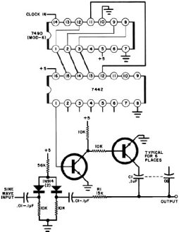
Fig. 2 - Circuit of an experimental digital filter for the audio
range.
In the simple circuit shown in Fig. 1A, with the six-position switch in position
1, and with an audio sine wave applied to the input, the first capacitor will start
to. charge up toward the signal's peak voltage. If S1 is switched to the next capacitor
when the voltage across the first capacitor has reached the average value for that
portion of the sine wave, the switch makes another step.
Therefore, as S1 rotates around the six capacitors, each capacitor receives a
charge whose value depends on the average value of the sine wave at its portion
of the waveform. The charges on the capacitors can be represented by the step curve
in Fig. 1B. Of course, the switch must be synchronized with the input sine wave.
If the input and switching frequencies are not synchronized, the average voltages
stored in each capacitor will differ and will drop very rapidly on each side of
the switching frequency. This is the basis of digital filtering; and because of
the synchronization system, tuning the filter to any desired frequency is primarily
a matter of "tuning" the switching oscillator. Component values for the resistance
and capacitance are not very critical.
The circuit of an experimental digital filter for the audio range is shown. in
Fig. 2. This circuit consists of a conventional mod-6 counter (7490) driving a BCD-to-decimal
counter (7442). The audio input to be filtered is passed through a simple clipper
and then coupled to the digital filter consisting of R1 and the six transistor-switched
capacitors (C1 through C6). The digital logic and transistors form the switch in
Fig. 1A. The digital clock that actually tunes the filter can be any variable-frequency
triggering source at six times the required filter frequency.
To tune the filter, connect the audio input to the clipper and a scope to the
output. For a dual-channel scope, use the second channel to observe the sinewave
input. Care must be taken in tuning the variable clock since the Q of the circuit
is high and the filtering action might be missed. As the input is tuned up further
in frequency, a peaking in the digitized waveform will be reached at the harmonics
of the original setup, with the steps getting coarser each time. This will happen
until the harmonic number corresponding to the number of switching positions is
reached (six, in this case). There will then be no output, but there will be at
the next harmonic. As each harmonic is viewed, it will be lower in amplitude and
coarser.
The filtered output signal is a distorted version of the original input so the
output can not be used as a sine wave. However, it is useful for triggering other
circuits. The bandwidth of the filter remains substantially the same even when the
filter frequency is changed. Once built, to change the filter's center frequency,
it is only necessary to change the clock frequency to the TTL counter (7490), with
the frequency six times the input. The number of switched capacitors is not limited
to six but can be any number from a minimum of three to as many as required. The
larger the number of capacitors, the smoother the displayed waveform.
The number of capacitors also determines the clock frequency. With six capacitors,
the clock must be six times higher in frequency than the input. With five switched
capacitors, the clock must be five times higher than the input signal, etc.
Posted July 22, 2022
|