|
May 1973 Popular Electronics
 Table of Contents Table of Contents
Wax nostalgic about and learn from the history of early electronics. See articles
from
Popular Electronics,
published October 1954 - April 1985. All copyrights are hereby acknowledged.
|
EIRP - effective isotropic radiated
power - is an important parameter when calculating both intentional and unintentional
electromagnetic emissions. EIRP is a vector quantity that accounts for both power (magnitude)
and 3-dimensional coordinates (direction). It includes antenna directivity that concentrates
power in a particular direction rather than distributing it equally in all directions
(e.g., isotropically). Effective radiated power factors in modulation type and power
envelope shape as well. Knowing how to measure that quantities can make the difference
between passing and failing FCC (or other countries' spectrum regulating bodies) certification.
How to Calculate Actual RF Output and Some Ways to Improve It
By Gladden B. Houck, Jr.
 Maximum effective radiated transmitter power is the
aim of all CB and ham radio operators. This is evident from the fact that so much effort
and money go into improving transmitter efficiency-matching devices, tuning couplers,
SWR bridges, beam antennas, etc. There are many factors involved, actually, in the struggle
to get maximum r-f output. Some are more important than others; but all are worth reviewing. Maximum effective radiated transmitter power is the
aim of all CB and ham radio operators. This is evident from the fact that so much effort
and money go into improving transmitter efficiency-matching devices, tuning couplers,
SWR bridges, beam antennas, etc. There are many factors involved, actually, in the struggle
to get maximum r-f output. Some are more important than others; but all are worth reviewing.
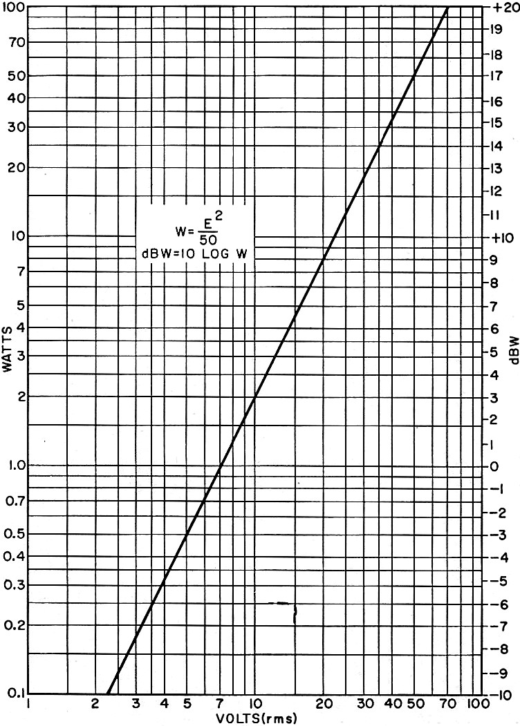
To start with, just how does one measure transmitter power output? One way is to use
a commercial r-f wattmeter. An alternate method is to measure the voltage generated across
a 50-ohm load with a conventional voltmeter using a high-frequency probe that will operate
at the frequency of interest. This measured voltage can be converted into approximate
r-f power for a 50-ohm load by using the curve in Fig. 1.

Fig. 1 - Converting volts to watts and dBW.
A less accurate method of determining r-f power output is to measure the dc power
(voltage and current) supplied to the power amplifier when it is loaded by the proper
antenna and tuned to resonance. The efficiency of this stage can be assumed to be about
60%, unless you have an actual figure supplied by the manufacturer. Thus, if the final
stage in a CB rig has about 13.2 volts on the collector and the collector current is
380 mA, the legal dc input rating of 5 watts is obtained. With 60% efficiency, this would
result in 3 watts of r-f at the output terminal.
To keep all computations in terms that point up the relative importance of any improvement,
a dBW rating is used. By using the scales in Fig. 1, we see that 3 watts is equivalent
to 4.8 dBW. This approach is based on zero dB for one watt.
The least change in dB levels that the ear can notice is about 3 dB (a power level
change of 2 to 1). If the transmitter described above had a 100% efficiency, its output
would be 5 watts (7 dBW), less than twice the level of the original 4.8 dBW, a barely
discernible improvement.
Line Losses. Transmission line losses are of two types: direct losses
and reflected mismatch losses. Direct losses are easy to determine since they are proportional
to the length of the transmission line, and they depend on the type of coaxial cable
used. One of the common types of cable employed for connecting the transmitter to the
antenna is RG-58/U. It has a loss rating of 0.022 dB per foot. If we assume that a typical
base station uses about 60 feet of cable, this means a direct cable loss of -1.32 dB,
where the minus sign indicates a loss. Using the same length of RG-8/U cable with a rating
of only 0.01 dB per foot, the direct cable loss is -0.6 dB. This shows that the selection
of coaxial cable can make a big difference in the transmitted signal level.
Reflected losses are measured by using an SWR bridge or an in-line wattmeter. The
proper place to make these measurements is at the connection between the transmission
line and the antenna. Measurements made at the transmitter end of the cable, although
valid, are always lower due to the cable losses which attenuate both the direct and reflected
signals to the bridge.
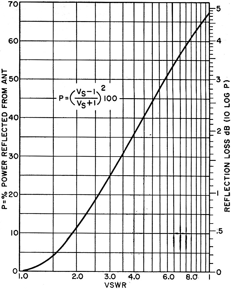
The chart in Fig. 2 provides a means of converting SWR and reflected power into dB
losses. If a typical antenna system has a measured SWR of 2.0, Fig. 2 shows that the
loss is -0.5 dB.
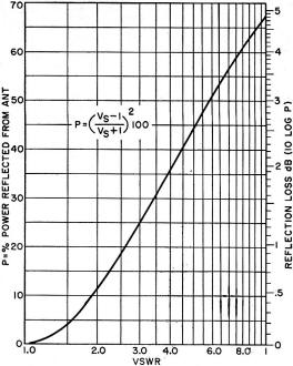
Fig. 2 - Finding reflectance loss from SWR.
Antenna Gain. The gain of an antenna is specified by its manufacturer
in terms of dB as compared to a standard dipole. Thus a simple whip antenna about 96"
long has a gain of about +2.15 dB, while a multi-element beam antenna may have a gain
of +11 dB or more. Since the gain of an antenna is difficult to measure without special
equipment, it is usually necessary to take the manufacturer's word for it.
If we assume that a rig has 3 watts of r-f output at the transmitter, 60 feet of RG-58/U
coaxial cable, an SWR of 2.0, and a beam antenna having +11 dB gain. These figures add
up as follows: (+4.8) + (-1.32) + (-0.5) + (+11) = +14 dBW. Using Fig. 1, this converts
to 25 watts of equivalent power.
Improvements in the transmission system by lowering the SWR or changing the cable
to RG-8/U might raise the figure from +14 dBW to +15 dBW (effective radiated power of
32 watts). Note that this would only improve the received signal strength by 16% which
is not enough to make that much difference, though every little bit helps.
For CB'ers and hams, the best thing to do is to use a directional high-gain multi-element
beam antenna. Antennas of this type provide a dramatic improvement in transmission and
also assist in reception. Since a beam antenna concentrates the energy (for both transmission
and reception) in a "tear-drop" pattern, with the sharp end of the pattern at the antenna
proper, it focuses most of the transmitted energy toward the receiver at which it is
aimed and also provides much less pickup in the other directions. This means a considerable
reduction in the pickup of unwanted Signals. By properly aiming the antenna, distant
transmission and reception are considerably improved.
In some situations, it is necessary to connect the SWR bridge at the junction of the
transmission line and the transmitter. Indications obtained in this manner must be corrected
for transmission line losses, with the curve in Fig. 2 used to convert SWR to dB of reflected
power. Since the transmission line losses affect the SWR in both directions, the effect
is to double the dB correction. Thus, if the SWR at the transmitter is 1.6, the reflected
loss is 0.2 dB. If the line losses are 1.0 dB each way, the total for SWR correction
is 2.2 dB.
Posted January 19, 2018
|