May 1959 Popular Electronics
 Table of Contents Table of Contents
Wax nostalgic about and learn from the history of early electronics. See articles
from
Popular Electronics,
published October 1954 - April 1985. All copyrights are hereby acknowledged.
|
Here are a few more electronics
conundrums with which to exercise the old noodle. These are puzzlers from a 1959
issue of Popular Electronics magazine, but at least one of them (#4) will likely prove to
be a real stickler unless you have seen a similar resistor mesh problem before
(here is my solution for the
resistor cube equivalent resistance).
There are no tube circuits to use as an excuse for not attempting them - just resistors,
batteries, switches, meters, a motor, and a couple light bulbs. All four would be
fair game to present to an interviewee to see where he/she stands on basic circuit
analysis. (see also the April
Electronic Sticklers)
Electronic Sticklers
These four thought twisters are arranged in order of increasing difficulty.
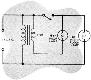 1) Happy Snap (left), having only an s.p.s.t. switch, wanted
to turn on a floodlight and a pilot light on the control board at the same time.
Expecting no trouble, he wired his setup as shown. After double-checking his connections,
he held his breath and inserted the wall plug. Things didn't quite work out. Do
you have any idea why? 1) Happy Snap (left), having only an s.p.s.t. switch, wanted
to turn on a floodlight and a pilot light on the control board at the same time.
Expecting no trouble, he wired his setup as shown. After double-checking his connections,
he held his breath and inserted the wall plug. Things didn't quite work out. Do
you have any idea why?
-Robert L. Noland
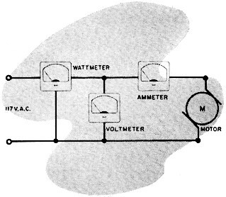
2) Dewey Dubblecheck, who believes in making all measurements
twice, connected a voltmeter and an ammeter to measure the power drawn in this circuit
(right).
Using the formula: W = E x I, he found that the motor drew 40 watts. He made the
measurement again, this time using a standard wattmeter, and read only 30 watts.
Dewey is puzzled - are you?
-Donald R. Wesson
 3) Sam Addit made this simple computer
(left) to add any
numbers from 1 to 6. The resistors were adjusted so that if battery #1 were switched
in, the 0-15 voltmeter would read 1, switching in battery #2 would give a reading
of 2, and so on. He figured that if a combination like 2 and 5 were used, the meter
would read 7. What did it actually read ? 3) Sam Addit made this simple computer
(left) to add any
numbers from 1 to 6. The resistors were adjusted so that if battery #1 were switched
in, the 0-15 voltmeter would read 1, switching in battery #2 would give a reading
of 2, and so on. He figured that if a combination like 2 and 5 were used, the meter
would read 7. What did it actually read ?
-Hal Carlson
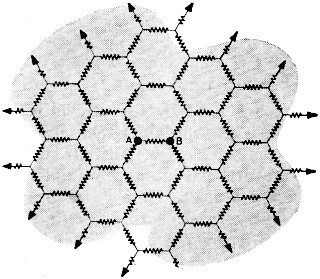 4) Network has a mesh of 1-ohm resistors connected
as shown and extending across his living room floor. Some day he hopes to extend
the mesh all the way to infinity - and maybe even beyond. Can you calculate what
the resistance will be between points "A" and "B" when his "tangled web" is finished? 4) Network has a mesh of 1-ohm resistors connected
as shown and extending across his living room floor. Some day he hopes to extend
the mesh all the way to infinity - and maybe even beyond. Can you calculate what
the resistance will be between points "A" and "B" when his "tangled web" is finished?
-Roy S. Reichert & Gene Harris
Answers to Electronic Sticklers
1. With the switch off, the lights will be in series across 117 volts ±6 volts.
Pilot light will pop first, then the floodlight will go out.
2. Dewey failed to consider power factor when he made his original measurement
with a voltmeter and ammeter. The wattmeter automatically took power factor into
consideration. In this circuit the power factor is 0.75.
3. The reading would be 5 because the batteries are connected in parallel. Actually,
unless the resistors are very large in value, the meter will read some value between
2 and 5 due to the loop current set up in the parallel circuit.
4. Although it is not practical to construct an infinite mesh, you can solve
this problem by using a variation of the constant current method for solving network
problems.
Assume that a battery is connected to the mesh in such a way that one terminal
of the battery is connected to point "A" and the other terminal is connected at
infinity. The size and polarity of the battery is such that 1 ampere of current
flows "into the paper" at point "A". Since the three resistors connected to point
"A" are all equal (1 ohm) and the surrounding mesh is symmetrical, the current divides
equally in the three branches. Hence, the current in the resistor between "A" and
"B" is 1/3 ampere (ia).
Now connect a second battery in a similar fashion, only in this case, while one
terminal again connects at infinity, the other terminal is connected to point "B".
The size and polarity of this battery is such that 1 ampere of current flows "out
of the paper" at "B". Again, for the same reason, the current divides equally. Hence,
an additional 1/3 ampere (ib) flows through the resistor between "A"
and "B" in the same direction as the current from the first battery. Since one terminal
of each battery is connected at infinity, the two currents at this point are equal
and opposite; therefore, they cancel. The infinite extremes of the mesh may be neglected.
It can be seen that a total current through the resistor (ia + ib)
is 2/3 ampere. Since this resistor equals 1 ohm, the voltage drop across it will
be 2/3 volt. It follows then that since 1 ampere of current flows into point "A"
and out of point "B," and the voltage drop from "A" to "B" is 2/3 volt, the total
mesh resistance is: R = E/1, or 2/3 volt/1 ampere, or 2/3 of an ohm.
If you know of a tricky Electronic Stickler, send it in with the solution to
the editors of POPULAR ELECTRONICS. If it is accepted, we will send you a $5 check.
Write each Stickler you would like to submit on the back of a postcard. Submit as
many postcards as you like but, please, just one Stickler per postcard. Send to:
POPULAR ELECTRONICS STICKLERS, One Park Ave., New York 16, N. Y. Sorry, but we will
not be able to return unused Sticklers.
Posted August 4, 2021
(updated from original post on 2/7/2013)
|