|
April 1973 Popular Electronics
 Table of Contents Table of Contents
Wax nostalgic about and learn from the history of early electronics. See articles
from
Popular Electronics,
published October 1954 - April 1985. All copyrights are hereby acknowledged.
|
The April 1973 issue of
Popular Electronics magazine concentrated on antennas for everything from citizens
band (CB) radios to televisions and amateur radio. This particular article covers
a compact, multi-band Ham antenna with a minimal level of skill and components required.
Construction and tuning tips are offered. It includes the popular 10-, 15-, 20-,
40-, and 80-meter bands. Standing wave ratio (SWR) plots are shown for all four
bands. If I had time, it would be interesting to enter the dimensions into
EZNEC (now free) to see what kind of
performance it predicts.
Multi-Dipole Antenna Has Low SWR and Uses No Traps
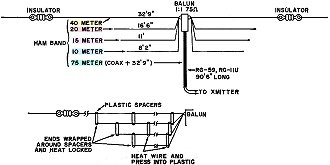
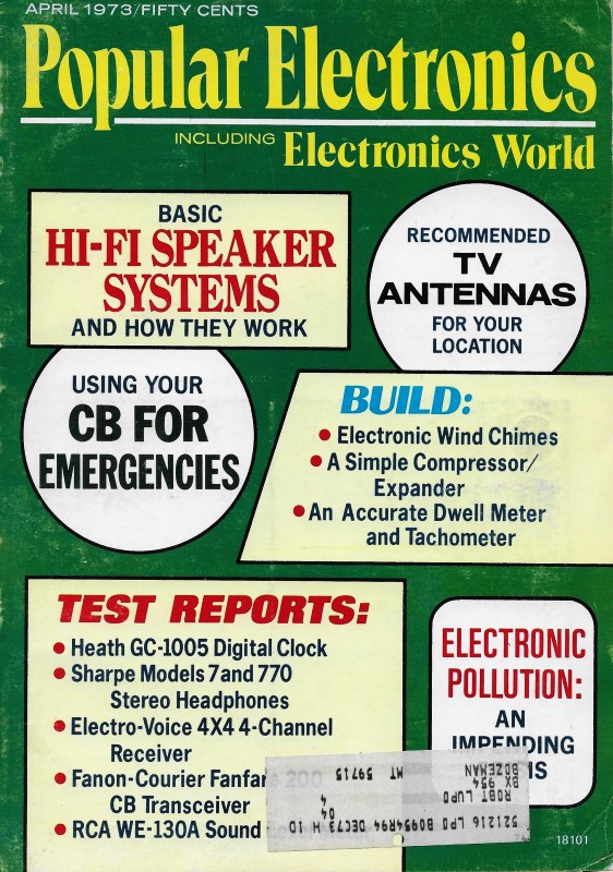
Fig. 1 - Method of constructing the multi-dipole antenna.
If space is at a premium, use inverted V approach.
By Richard A. Yommus, W2DMK
Many hams encounter problems in erecting just one antenna, so the thought of
needing antennas for five bands seems out of the question. However, with about 70
feet of antenna space (somewhat less if the inverted V configuration is used) a
five-band (75, 40, 20, 15, and 10 meters) antenna can be erected. The antenna has
a separate dipole for each band and does not use any traps.
As shown in Fig. 1, the antenna is a Single-feed, four-band, separate dipole
system, using a conventional, commercially available balun transformer (1:1, 75
ohms) for a symmetrical radiated pattern on these bands. The dipoles are individually
cut to any given frequency within a band using the equation L = 468/F, where L is
in feet and F in MHz. For general use, the dipoles should be resonant at the center
of each band.
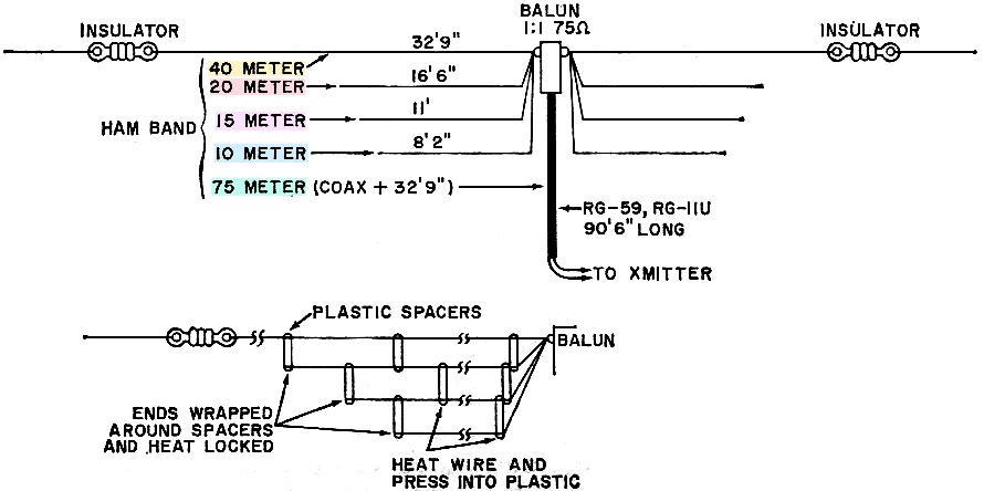
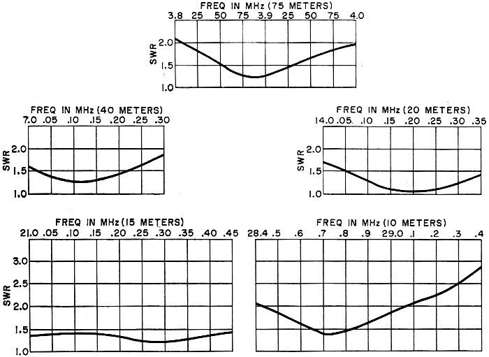
On 40 and 20 meters, the antenna maintains a fairly consistent SWR of less than
2:1 (see Fig. 2), while on 15 meters, the curve is flatter with hardly any
change in SWR from the low end to the high end of the band. On the 10-meter band,
the usable bandwidth is about 500 kHz on either side of resonance before the SWR
becomes excessive.
Using multiple dipoles with one feedline is a common practice among hams, but
the fact still remains that, for 80-meter operation, it takes between 120 and 135
feet of wire to radiate effectively. Using the popular trap-type antenna on 75-80
meters, the overall length usually exceeds 100 feet with an extremely narrow operating
frequency range.
The coaxial feedline does not represent a full wavelength electrically on the
40-meter band. At 7.15 MHz, the physical length of the coax is determined by (492/F)
times 2 times VF, where F is in MHz and VF is 0.66 when RG-59 or RG-11U, 75-ohm
coax is used. For 7.15 MHz, then the length is 90' 6". The flat top overall length
at 7.15 MHz is determined from 468/F or 65' 6". This is divided by two to give 32'
9". By adding the coax length of 90' 6" to the 32' 9" of the divided flat top, a
resonant length of 123' 3" is obtained, which represents a half wave of slightly
below 3.85 MHz.
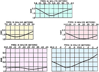
Fig. 2 - Standing wave ratios for the antenna on various
bands. On 40 and 20 meters, SWR is fairly consistent; but on 15 meters, it is relatively
flat.
The transmission line can be fed from the pi network of a transmitter or transceiver
without the aid of an additional antenna coupler, although a coupler could tune
out any reactance.
The SWR is excellent for about 200 kHz of the 75-meter phone band, and does not
exceed 2:1 at this point. On this band only, the inner and outer conductors of the
coax are tied together at the transmitter end. In the event that operation is desired
on the low end of 80 meters, a length of wire can be used to resonate at the desired
frequency. The wire is then switched out when operation at the high end is desired.
This additional length of wire can be simulated in an antenna coupler or by a simple
L network. The radiated pattern on 75 meters is essentially omnidirectional with
both vertical and horizontal polarization.
Construction. The 40-meter antenna should be made of copper-clad
steel wire to provide strength. Both the wire and plastic spacers used in the antenna
can be obtained from a length of 450-ohm open TV transmission line, or commercially
available air dielectric transmission lines. Each end of the 40-meter dipole is
connected to an insulator, while the center is tied to the connectors on the balun.
The remaining dipoles are suspended from the 40-meter dipole with the plastic spacers
that come with the transmission line. Short lengths of plastic rod may also be used.
In most cases, it is sufficient to heat the wire and push it into the plastic, where
it will be firmly gripped when the wire cools. The spacers are about 6" apart along
the lines. The center of each dipole is connected in parallel with the one above
it, to a lug on the balun.
The coax transmission line should be kept away from buildings, trees, power lines,
metal surfaces, etc., when being fed as a resonant line. For the same reason, it
should also be outdoors as much as possible. Keep the transmission line at right
angles to the flat top dipoles if possible.
The balun transformer has no appreciable loss when connected as described here
and appears as a small inductance in series with the coax. Since the differential
voltage across it is very small, there is no possibility of its burning out.
To experiment with keeping the SWR fairly consistent from one band to another,
add about 3' of 75-ohm coax to the 90' 6" length. Before trimming the coax, make
sure that all dipoles are resonant at the center of each band. Then, trim off 6"
of coax at a time, until the SWR becomes consistent on each band. The extra length
of coax will not impair operation on 75 meters; but it will shift the frequency
slightly lower than 3.850 MHz.
Posted February 15, 2024
(updated from original
post on 10/24/2017)
|