|
August 1960 Popular Electronics
 Table
of Contents Table
of Contents
Wax nostalgic about and learn from the history of early electronics. See articles
from
Popular Electronics,
published October 1954 - April 1985. All copyrights are hereby acknowledged.
|
Most regular RF Cafe visitors
will probably not be too interested in this 1960 Popular Electronics magazine
article, but there are a lot of people who build and/or repair vintage radio gear
and search the Internet for helpful information. Having built a couple crystal radio
sets as a kid, I've always been amazed at how a few picowatts of RF energy can be
received, processed, and heard through an ear plug without the need for external
power from a battery.
Speaking of crystal radios, I remember one time while working as an electrician
in Annapolis, Maryland, (prior to entering electronics) I had a telephone handset
for use in communicating with other electricians in a building I was wiring, and
it picked up the local AM radio station. A pair of the old style handsets with carbon
microphones would, with the help of a single 'D' cell in series, function as a very
acceptable intercom system using two standard electrical wires between them. I could
go on the building roof to work on a compressor unit and communicate with a guy
in the panel room simply by having us connect to the same two wires (usually 14
or 12 gauge). Anyway, the microphone evidently acted as a rectifier, possibly due
to dirty spring contacts against the element, and processed the AM radio signal.
It was clear as a bell. After hearing the broadcast, I looked around (remember I
was on the roof) and saw that I was about a block away from an AM antenna tower.
Mystery solved. I never have had a dental filling receive a radio broadcast.
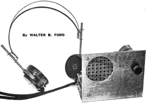
High Power Crystal Set
By Walter B. Ford
Voltage-doubler circuit drives miniature speaker
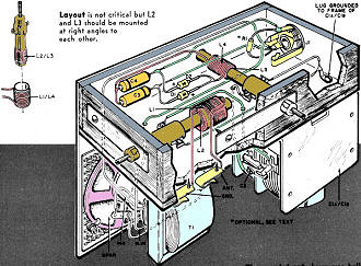
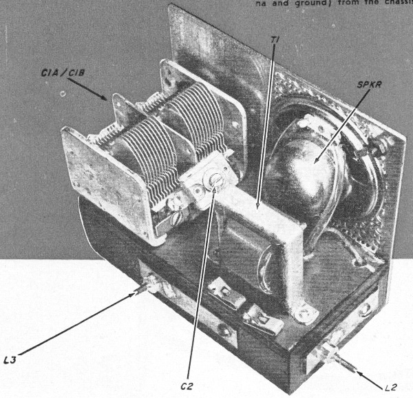
Layout is not critical but L2 and L3 should be mounted at right
angles to each other.

The crystal set shown was built on a wooden chassis. If a metal
chassis is used, be sure to insulate the Fahnestock clips (antenna and ground) from
the chassis.
|
Here's a pint-sized crystal radio with enough oomph to drive a 2 1/2" speaker.
This little unit's selectivity is far better than you'd expect to find in a crystal
receiver and volume is equal to that obtained with sets using a transistor. No external
power source is required.
The unusual selectivity of this radio is due to its special double-tuned circuit.
A pair of diodes connected as a voltage-doubler provides the extra kick to operate
the small speaker. An output jack is provided for headphone listening and for connecting
the set to an amplifier.
Construction.
The model was built on a 2 1/2" x 4 1/2" wooden chassis with a 3 1/2" x 4 1/2"
metal front panel. However, size is not critical, and other materials can be substituted
if desired.
Two standard ferrite loopsticks, L2, and L3, are used. Both must be modified
by the addition of a second winding, L1 and L4, respectively. Each of the added
windings consists of 22 turns of No. 24 cotton-covered wire wound on a small cardboard
tube as shown on the pictorial. (Actually, any wire size from No. 22 to No. 28 with
cotton or enamel insulation will do the job.) The diameter of the cardboard tube
should be slightly larger than L2 and L3 so that L1 and L4 will slip over L2 and
L3 easily.

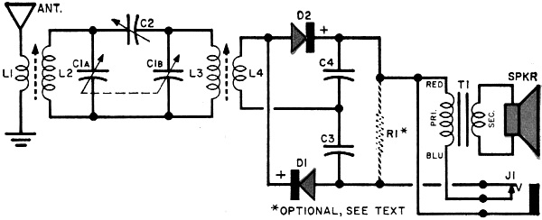
Crystal radio schematic
Parts List
C1a/C1b - 2-gang 365-µµf. variable capacitor (Lafayette
MS-142 or equivalent)
C2 - 180-µµf. compression-type trimmer capacitor
C3, C4 - .005-µf. fixed capacitor
D1, D2 - IN34A diode
J1 - Closed-circuit phone jack
L1, L4 - 22 turns of No. 24 cotton-covered wire (see text)
L2, L3 - Ferrite antenna coil (Miller 6300 or equivalent)
R1 - 47,000-ohm, 1/2-watt resistor (see text)
T1 - Replacement-type output transformer; 3000-to 10,000-ohm primary; 4-ohm secondary
Speaker - 2 1/2" speaker, 4-ohm voice coil (Lafayette SK-65 or equivalent
Misc. - Hardware, wood, aluminum sheet, Fahnestock clips, etc.
For phone operation only, the speaker, transformer, and resistor R1 can be omitted.
In this case, connect high-impedance phones in place of R1.
Resistor R1 is used only for feeding the set into an amplifier; it should be
omitted for both earphone and loudspeaker operation. Trimmer capacitor C2 should
be soldered across the stator terminals of two-gang variable capacitor C1a/C1b,
as shown. The speaker and output transformer can be mounted wherever convenient.
After all of the parts have been mounted on the chassis, wire them together following
the schematic and pictorial diagrams. Be sure that diodes D1 and D2 and capacitors
C3 and C4 are correctly polarized.
Alignment and Operation
To align the receiver, first connect it to an antenna and ground. (The optimum
length of the antenna varies with location, but 50 feet will usually be suitable
in areas serviced by several broadcast stations.) Next, plug in a high-impedance
earphone at jack J1. Tune in a station near the high-frequency end of the broadcast
band - say 1500 kc. - and adjust the trimmer capacitors on variable capacitor C1a/C1b
for the loudest signal.
Trimmer capacitor C2 should then be adjusted for the best selectivity and volume
over the entire broadcast band. Finally, coils L1 and L4 can be optimally positioned
by sliding them back and forth over coils L2 and L3. If a nearby station interferes
with reception of a weaker one, tune the slug on L2 for minimum interference.
For loudspeaker operation, simply unplug the earphone from J1 - strong local
stations should come in with fair volume. To operate the set as an AM tuner, wire
R1 in place and connect J1 to the crystal-phono input of a preamplifier or integrated
amplifier. The set should give excellent results with a quality hi-fi system.
How It Works
The receiver employs a double-tuned circuit feeding a crystal-diode voltage-doubler/detector
which drives a small speaker. In operation, r.f. signals picked up by the antenna
system are induced into coil L2 from coil L1. The desired signal is selected by
tuned circuit C1a-L2 and coupled through capacitor C2 to a second tuned circuit,
C1b-L3, which improves the selectivity by narrowing the r.f. bandpass. The twice-tuned
r.f. signal is then induced into coil L4 from coil L3.
The positive half of the r.f. signal appearing across L4 passes through diode
D2 to charge capacitor C4; the negative half of the signal passes through diode
D1 to charge capacitor C3. Polarities of the charges on C3 and C4 are such that
the effective voltage is doubled. This voltage appears across the primary of output
transformer T1, which changes the high impedance at the output of diodes D1 and
D2 to the low impedance required by the speaker.
When high-impedance earphones are plugged into closed-circuit jack J1, the speaker
is disconnected and the output from the diodes feeds directly into the earphones.
Optional load resistor R1 is placed across the output of the diodes when the receiver
is used with an amplifier.
Posted November 29, 2021
(updated from original post on 6/24/2013)
|