February 1960 Popular Electronics |
 Table of Contents Table of Contents
Wax nostalgic about and learn from the history of early electronics. See articles
from
Popular Electronics,
published October 1954 - April 1985. All copyrights are hereby acknowledged.
|
Even in the year 2022, there
is a huge cadre of turntable aficionados out there whose players can only be taken
from them by prying them from their, cold, dead hands. Look at all the buying and
selling of turntables that takes place on
eBay if you have any doubt (the search I just did turned up more
than 800 items). I remember in my U.S. Air Force days, the only time ever lived
in mass group quarters (no college dorms for me), guys were in heated competition
against each other over who could accumulate the most extensive and expensive hi-fi
gear. A large percentage in my barracks were mobile communications types, and they
seemed to spend about as much time adjusting their turntables, reel-to-reel tape
decks, and receivers for ultimate performance. Entire beer and pizza parties were
centered around topics like balancing tone arms. As with most subjects where many
"experts" debate, no two could agree on the best method. Here's a little sage advice
from a 1960 issue of Popular Electronics magazine in case you're not a
seasoned tone arm balancer.
Inside the Hi-Fi Tone Arm
 By Joseph Marshall By Joseph MarshallIf you think the tone arm
of a high-fidelity system can't seriously affect a record's sound quality, you are
wrong. Actually, a poorly designed or improperly adjusted arm can do more damage
to the sound quality of a record than perhaps any other part of the system. And
with the advent of stereo, the demands imposed upon the tone arm have become much
greater than they were in the old mono days.
Tracking Error. When a master record is cut, the cutting head
is moved across the record by a lathe screw and is always at a 90° angle to the
radius of the record. Ideally, in playing back the record, this relationship should
be maintained. It would be possible to do so if the pickup traveled along a radial
track running from the center of the record to some point outside the turntable.
But this solution would raise another serious problem: the stylus would have
to drag the cartridge along some kind of rod or rail. It is very difficult to design
a method to accomplish this end without putting an excessive load on the stylus.
One or two acceptable radial arms have been produced, but most manufacturers find
it more satisfactory to pivot the arm outside the turntable.
Clearly, an arm that is pivoted outside the record cannot move along the straight
line of the radius. It will necessarily trace a curve. There may be one or two points
at which the arm precisely reproduces the angle of the cutting head, but at all
other points it will depart from the original cutting angle to some extent. This
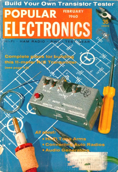
angular deviation is called "tracking error" and is illustrated in Fig. 1 on
page 48. Tracking error can be considerable. For example, if you were to mount a
straight 8" arm so that the point of the stylus passed over the turntable spindle,
the error would vary from about 22° at the outermost groove to 7 1/2° on the innermost
groove. The resulting harmonic distortion would run well over 5% and (at 22° tracking
error) the maximum stereo separation on a stereo disc would be limited to only 30
db - not taking into consideration the separation losses in the cartridge and amplifier.
To meet high-fidelity standards, tracking error should be no more than 1.4° on the
inner-most grooves and 4° on the outermost grooves. At first consideration it would
seem impossible to keep tracking error this low, but ways have been found to do
it.
Fig. 1 - Tracking error occurs in the area shaded with the
diagonal lines.
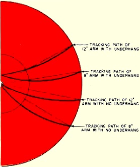
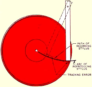
Fig. 2 - Effects of various amounts of underhang and differing
arm lengths on the amount of tracking error.
For one thing, the longer the arm, the shallower the arc it will trace becomes
and the closer it will come to the straight line of a radius. If we could use an
arm several feet long, the arc could be close enough to a straight line to provide
a very small tracking error. But an arm longer than 16 to 18 inches is usually out
of the question, and even these lengths are longer than is convenient for most home
applications.
Fig. 1. Tracking error occurs in the area shaded with the diagonal lines.
Decreasing Tracking Error. A more practical way of reducing
tracking error takes into account the fact that records are recorded only on the
outer three or four inches, so there is no point in worrying about tracking the
inner two inches. If we mount the arm a little farther out, it will under hang the
turntable spindle and the stylus will come short of the center of the record. This
will reduce tracking error, especially on the innermost grooves where it is most
serious. The effects of arm length and underhang on tracking error are indicated
in Fig. 2.
Another way of improving tracking is shown in Fig. 3. The lower arc is the
path of a straight 8" arm with no underhang or overhang. The solid lines indicate
the actual path of the arm and stylus, while the broken lines indicate the path
the arm would have to take to provide perfect tracking. Note that on the outermost
groove the tracking error is about 22°. Now suppose that we offset the head of the
same arm by about 22°. The angle of the arm at the point where the needle rides
the outer groove would be exactly right. As the arm moved inward, however, an error
would begin to occur. At the halfway point, there would be an error of about 8°
instead of the 14° we had with the straight arm. Beyond this point, things would
get worse and the error would be greater than before.
However, we can correct this situation by moving the arm closer to the turntable
so that the arm overhangs the spindle. This maneuver will have the effect of reducing
the offset of the arm at the inner grooves while maintaining it at the outer grooves.
By choosing optimum values of offset angle and amount of overhang, we can achieve
a tremendous improvement in tracking. The upper arc in Fig. 3 is for an 8"
arm with an offset of 28°. There are now two points where there is no tracking error
at all, and the error is 2° or under at all other points.
Offsetting a longer arm permits even better tracking. The longer arm requires
less offset and a smaller overhang. Practically all arms have an offset, although
sometimes the offset is not obvious. Thus, although the Pickering 190D and the Shure
"Studio Dynetic" arms appear to be straight, they actually provide offsets by the
way the pickup is oriented in its mounting. By combining these various ways of improving
tracking, modern tone arms achieve tracking errors of 1° maximum and thus prevent
degradation of fidelity and stereo separation.
Free Movement. Assuming the arm has low tracking error, its
next problem is to move freely up and down and from side to side. Unrestricted lateral
movement is necessary because the stylus has to pull the arm across the record.
Vertical freedom is necessary because the arm must be able to track warped records.
There are two general approaches in designing a tone arm that will permit these
two types of motion. One is to use the same pivot point for both the vertical and
the lateral movement. In this design, the entire arm moves up and down when it tracks
a warped record. If something weren't done to prevent it, this would place the entire
weight of the arm on the stylus.
(A) Counterweight balances weight of arm
(B) Tension of spring balances arm
(C) Counterweight provides balance and small spring adjusts stylus pressure
(D) Spring pulls up hinged section of arm to balance downward pull of cartridge
Weight is nothing more than the force of gravity working on the mass of an object.
If the force of gravity is counteracted by another force, weight can be reduced,
or in effect, eliminated at a given point in space. One way to do this is to balance
one weight with an equal weight or counterweight. We can extend the arm on the other
side of the pivot point, install a counterweight on it, and adjust it to achieve
a near balance.
Actually we do not want an exact balance. The stylus must be held in place in
the groove by a light pressure. So we adjust the counterweight to provide a stylus
pressure of from 1 to 8 grams. A mass so nearly balanced becomes very light and
easy to lift - as those of us know who have used a see-saw with someone else of
nearly equal weight. The counterbalance approach to tone-arm design is shown in
Fig. 4 (A). The Grado, Pickering, and Rek-O-Kut arms are examples of this
approach.
Another way of applying a counteracting force is by means of a spring. See Fig. 4(B).
Here the pull of the spring is adjusted until it almost - but not quite - equals
the weight of the arm. The difference provides the needed stylus pressure. But the
trouble with this arrangement is that a spring is not a linear source of force.
It exerts less force as it compresses and therefore causes the arm to become, in
effect, heavier as it is raised. For this reason, spring balance is employed only
with arms in changers and manual players where the use of a counterweight balance
is not feasible because of various mechanical considerations.
However, several counterweight-balanced arms use a small spring for fine adjustments
of stylus pressure. See Fig. 4 (C). In this design, the arm is first balanced
with the counterweight and then the spring tension is increased to provide the proper
stylus pressure. Note that the spring pulls the arm toward the record and thus tends
to hold the stylus in place. Such arms have a high degree of stability and will
operate satisfactorily even if the turntable is not perfectly level. Some of the
newest arms - the ESL, the Audio Empire, and the Dynaco - employ the combined counter-weight
and spring-balance system.
The second approach to achieving free tone - arm movement is to use two pivot
points: one at the mounting point for lateral movement, and one somewhere between
this point and the cartridge for vertical movement. This technique is shown in Fig. 4(D).
Since only the end of the arm moves up and down, the amount of mass we have to deal
with is comparatively small, and a simple spring-balance system can serve nicely.
In most cases, little more than the weight of the cartridge has to be moved. The
Gray SAK-12 and Fairchild 280A arms are examples of this type of design. However,
in the Shure "Studio Dynetic" arm, a small counterweight on a threaded rod balances
the weight of the cartridge; this arm achieves high stability at stylus pressures
as low as 1 gram.

Fig. 3 - Comparison of the amount of tracking error from
an 8" straight arm with no overhang or underhang and an 8" offset arm with overhang.

Fig. 4 - Four ways to counteract the weight of the tone
arm and cartridge.
Whatever pivot arrangement is used, friction in the pivots should be as low as
possible. Many types of bearings are used in tone arms, and while each has its special
advantages, it seems that, with proper design, various types can produce equivalent
performance. The simple thrust bearing is used by Audax, Fairchild, Grado, Gray
(lateral), Shure, and Weathers. Ball bearings are used by Audio Empire, ESL, Garrard,
London-Scott, and Rek-O-Kut. The Dynaco features gimbal pivots in both bearings,
and Pickering and Stromberg-Carlson use a single needle-point suspension. In addition,
several arms employ viscous-damped bearings.
Viscous Damping. At first glance, viscous damping seems to violate
the principle of keeping friction low. A viscous-damped arm opposes any rapid and
sharp motion - such as being dropped onto the record accidentally. But at the speed
at which the arm customarily travels over a record, the friction of a viscous-damped
arm is insignificant.
Viscous damping has several advantages. First, it produces a high degree of stability
even at very low stylus pressures; the Weathers arm is stable with only one gram
of pressure. Secondly, it provides a high degree of damping against arm resonance,
another serious problem in arm design. Some degree of viscous damping is employed
in one or both pivots of the Gray, Weathers, Stromberg-Carlson, and London-Scott
arms.
Resonance of the arm at any frequency within the audio range must be avoided.
The simplest way to minimize the possibility of resonance is to make the arm out
of a material which is not prone to vibration in the audio range - such as wood.
Both Weathers and Grado make their arms out of wood. When other materials are used,
all the physical characteristics of the arm - such as shape, cross section, length,
and weight - must be carefully coordinated to keep the arm from resonating above
20 cps. A counterweight helps in solving this problem because its mass tends to
damp resonance.
It is highly desirable, especially with stereo records, to reduce stylus pressure
to the least amount necessary for good tracking. One way of achieving this reduction
is to design the arm specifically for the cartridge and tailor the characteristics
of the arm to complement the cartridge. Examples of such integrated combinations
are the Weathers, the Shure "Studio Dynetic," the Dynaco, and the London-Scott.
Though modern tone arms differ in many respects in their design approach to the
problem of providing good performance, they have all been specifically developed
to meet the highly critical demands of today's records and provide excellent results
when they are properly installed.
Posted July 13, 2022
(updated from original post on
1/9/2012)
|