|
|||||||||||||
 |
|||||||||||||
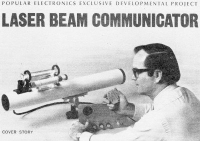
Popular Electronics Exclusive Developmental Project:
|
|||||||||||||
The ambition of amateur hobbyists has always amazed me. In practically every area of technology, amateurs have contributed significantly to the effort of pushing back the frontiers of ignorance by developing new applications, improving existing products, and demonstrating to commercial companies a need for new features or products. Many of those innovative hobbyists make a living in the field they choose for off-hours recreation. As a heavy reader of technology and hobby magazines of all sorts, I know this to be true for musicians, boaters, pilots, radio operators, gardeners, science experimenters, woodworkers, and many others. Levels of quality of finished products are awesome in the master class competitions. The amount of money spent by some for their "hobbies" is shocking. This laser communications article from the May 1970 Popular Electronics magazine is a prime example of that. The author uses off-the-shelf components to construct both the transmitter and receiving components. A quick tally of the most expensive parts - telescopes, laser module, photocell, power supplies - shows the project would have cost upward of $400. According to the U.S. Bureau of Labor Statistics' inflation calculator, $400 in 1970 money is the equivalent of about $3,056 in 2022 money. That's an expensive "toy." Popular Electronics Exclusive Developmental Project Laser Beam Communicator
Audio Modulate Our Low-Cost Laser Communicating by means of a laser beam is as fresh and new as the tomatoes picked from your garden tomorrow morning. The mere idea of being able to transmit information on a beam of coherent laser light suggests all sorts of possibilities for secret, non-jammable, interference-free communications. And it is possible today! Communications by laser beam offers several advantages over conventional radio links. Neither atmospheric lightning nor airborne electrical noise affects laser communications though they can completely ruin radio communications. On the debit side, however, laser performance is degraded, over any reasonable distance, by heavy fog, rain, snow, or terrestrial heat. Unlike radio, in which the signal is "sprayed" out over a wide area, a laser beam communications system operates on a line-of-sight basis and the beam is tight enough to provide excellent privacy. Of course, obstructions cannot be permitted to interrupt the beam but conventional optical mirrors can be used to bend the light beam around obstructions if necessary.
PE at the Smithsonian
Two approaches to laser communications are described in this article. The first
involves only a simple addition to the basic laser described in POPULAR ELECTRONICS
in December 1969. This system has a range of about 100 ft., and can be used for
experimenting within a room and provides a "breadboard" for use in understanding
modulated laser action. It also makes an excellent science fair project.
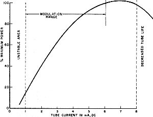
A pair of Popular Electronics laser communicators, similar to the one described in this article, is scheduled to be shown in operation at the Laser-10 exhibit at the Smithsonian Institution's National Museum of History and Technology in Washington, D.C. this spring and summer. Readers living in the area or visiting Washington will want to see this excellent exhibit, which features a wide variety of lasers in many unique applications. The POPULAR ELECTRONICS laser communicators will be set up to carry two-way conversations. The second approach uses a modulation and receiving scheme similar to the first but it operates through conventional low-cost telescopes to achieve a range of several miles (depending on atmospheric conditions). Laser Modulation. The light output of a gas laser such as the 0.5-mw helium-neon type described in our previous article is a function of the current flowing through the laser tube (see Fig. 1). At very low currents, the laser becomes unstable and tends to turn itself off. The light output increases reasonably linear with tube current up to approximately 5 mA. Above that, the light output drops drastically and tube life is decreased. If the current is centered on the middle of the linear portion of the curve and varied about that point, the light output can be made to swing in a linear fashion and very high modulation levels can be obtained.
Fig. 1 - Light output of the laser is a function of tube current. Modulation 90% or better can be obtained easily by this modulation method.
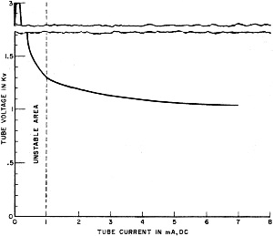
Fig. 2 - Negative-resistance characteristic of the laser shows that a large-value variable resistance is required for stable operation over the entire operating range.
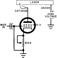
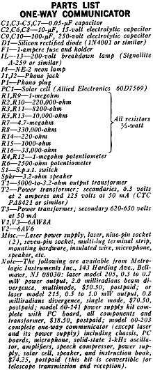
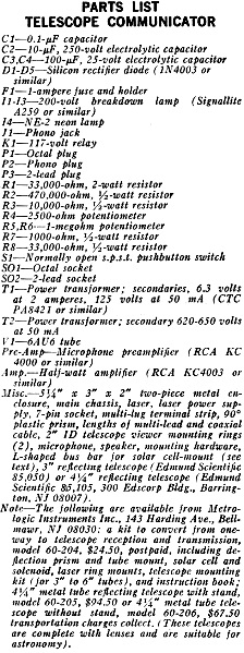
Fig. 3 - The basic amplitude modulator uses a conventional pentode in series with the laser. The suppressor grid is electrically connected to the cathode. A basic modulator circuit, using a pentode with a large dynamic resistance, is shown in Fig. 3. The pentode is in series with the laser tube and forms a simple amplitude modulator. The dynamic resistance of the pentode is a function of the applied audio signal on its control grid. A potentiometer in the cathode circuit of the pentode determines the basic operating resistance of the tube and, hence, the operating point of the laser. Once the latter point (located on the curve in Fig. 1) has been set by the bias potentiometer, an audio input to the pentode causes the laser current to fluctuate about the operating point and the emitted light is amplitude modulated. Almost any type of audio driver can be used to generate the input audio signal to the pentode. Basic Modulator. The circuit for converting the original laser project into a light-beam transceiver is shown in Fig. 4. A photograph of the finished project is shown in Fig. 5. A complete vacuum-tube system is used simply because a high resistance device is required and the tube that will do the job is inexpensive and readily available. In addition, the +175 and 6.3-volt sources required by the pentode can be used elsewhere in the circuit. The modulator circuit can be divided into two portions. The transmitter (V1) consists of the pentode modulator driven by the triode half of the tube acting as a microphone preamplifier. Potentiometer R4 provides modulation level control. The three gas tubes in series (I1-I3) are 200-volt breakdown lamps which chop off the high-voltage spikes that trigger the laser. Although the operating plate voltage of the tube is below its maximum rating, a much higher voltage spike is used to trigger the laser. The three gas lamps limit this spike to 600 volts. Unlike semiconductors, a vacuum tube can withstand an overvoltage for a short time. The trigger spike here lasts only about one millisecond so no damage can be done to the tube. If you can't locate the gas tubes called for in the Parts List, use any combination of conventional neon lamps that add up to approximately 600 volts. The receiving portion of the modulator consists of a three-stage conventional audio amplifier driven from the output of the solar cell. Unlike a conventional light-dependent resistor, a solar cell generates a voltage that is a function of the amount of light striking the photosensitive surface. Construction. If you built the original laser project, the same metal chassis may be used. Drill or punch holes for two 9-pin and one 7-pin tube sockets. These may be located on the top of the chassis, next to the laser tube. (Be sure to remove the laser tube when doing mechanical work on the chassis.) On the wall opposite the high-voltage laser power supply, mount the three potentiometers (R6, bias; R4, modulation level; and R12, receiver volume), the microphone input jack (J1), and the photocell input jack (J2) (see Fig. 5). Mount power transformer T2 on the outside of the chassis using the same mounting hardware as were used for the original 600-volt transformer. (It was T1; now it is T3.)
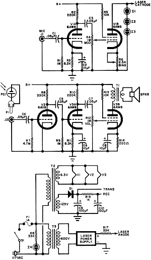
Fig. 4 - Other than the basic pentode modulator (V1B) circuit, either vacuum-tube or semiconductor audio amplifiers can be used for the remainder of the circuit. Once all the components are installed, wire up the circuit point-to-point (using terminal strips as required) following the circuit shown in Fig. 4. Of course, it is not necessary to use vacuum tubes for the microphone amplifier. You can use the 6AU6 pentode for the laser driver and, for the amplifier, anyone of several commercially available transistor amplifiers. The author used one of the new RCA IC kits - the KC4000 microphone preamplifier - in one model and found that it worked fine. The solid-state receiver consisted of a KC4000 microphone preamplifier for the photocell preamplifier and a KC4003 1/2-watt audio amplifier to drive the speaker.
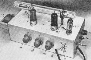
Fig. 5 - The prototype was built on the original laser chassis (December 1969 issue). Any other layout will do as long as the pentode modulator is as close as possible to the laser.
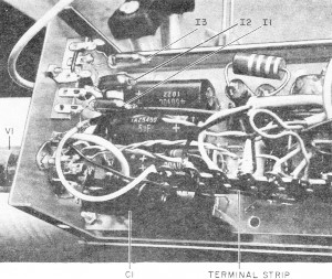
Internal layout of the prototype transceiver (above) showing the laser power supply mounted on one wall with the rest of the components occupying the remaining space. The internal arrangement of the telescope electronics (shown below) shows the modulator tube and its associated components arranged within its smaller metal enclosure.
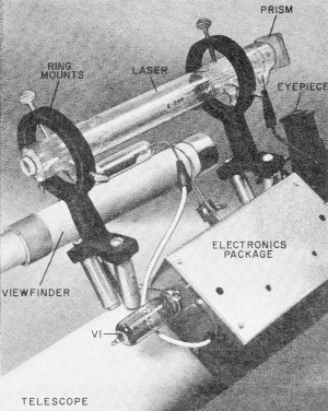
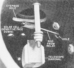
The complete telescope system can communicate as far as a 12-inch target can be clearly seen via the telescope. At night, this target will have to be illuminated. In good visibility, range can be very great but is dependent on certain conditions (see text). To assist distant communications, an optional 1-kHz audio oscillator is used to modulate the transmitter, and both ends must be "juggled" until the received audio tone is at a maximum. To get around opaque objects, a large-size front-surface mirror (not a ladies compact mirror) may be used to reflect the laser beam. Testing. Place the volume, modulation, and bias potentiometers in their minimum resistance positions. Connect up the speaker, photocell, and radio and turn on the power. The laser tube will start to blink at a low level until the modulation pentode warms up. Once the tube is hot, the laser will operate at its full brightness. A slight increase in the resistance of R6 should cause the laser beam to dim slightly. This shows that the bias control is operating properly. Now set the control for full brightness. Increasing the volume control should produce some hum in the speaker. If conventional room light is allowed to fall on the sensitive face of the solar cell, it will produce a distinctive hum. This is the reason the solar cell should be mounted in a dark tube. Separate the laser and the solar cell by a few feet and aim the beam at the receiver. Alternatively, aim the laser beam at a mirror so that it is reflected back to the cell. (The beam must be aimed straight down the cell tube and not at the interior wall.) With the laser beam shining on the solar cell at full brightness, turn on the radio, tune to a station, and plug in the earphone jack. On the laser chassis, turn up the receiver volume control and note that, as the hand is passed through the laser beam, a thump is heard in the speaker. Slightly reduce the bias control to dim the laser a little, and turn up the modulation control slightly. These two controls interact somewhat so you will have to "juggle" them for best modulation. Make sure that the radio volume is turned up sufficiently. Once the communicator is working, you can experiment with the controls and the circuit (always retaining the pentode as the laser modulator) to increase your understanding of laser communications. Optical Systems. Depending on how you want to use it, the laser communicator can be set up with anyone of three optical systems. The simplest, which can be used for point-to-point communications around a room (to a total of 100 ft round trip), is as described above, without any lenses. To improve the reception somewhat, a simple lens can be placed in the beam path at the receiver end to reduce the size of the diverged beam. The second type of optical system, requires the use of a set of binoculars, one eyepiece for the transmitter and the other for the receiver. Simple toy telescopes may also be used. The range for this type of system is a few hundred feet. For communicating over greater distances, a reasonably high-power telescope is necessary. Such a telescope, attached to the laser communicator, acts like a high-gain antenna on a conventional radio system. In both cases the transmitted and received signals get a boost from the "antenna." And in both cases, the telescope or antenna is used for both transmitting and receiving through a simple mechanical switching process. How far can you transmit using a telescope? It depends on a number of factors, the most important being beam divergence and atmospheric conditions. As the beam travels along its path, it tends to enlarge (diverge). This means that, although the beam leaving the laser is quite small (1 millimeter in the POPULAR ELECTRONICS laser), it does enlarge considerably - though not as much as a comparable beam of conventional light. Using a telescope improves this condition considerably. Atmospheric disturbances of the laser beam cause it to wander. As the beam of light is projected over a long distance, it may encounter various forms of air turbulence, such as localized temperature changes. In each of these turbulences, the density of the air changes and each change in density acts as a prism as the beam passes through it, changing the beam's direction slightly. The amount of wander can be as much as several feet per mile. In the still, relatively even temperature of morning, before the sun has had a chance to warm up the air, beam wander may be as little as a few inches per mile. In using a reflector telescope such as that described later in this article, the beam should be collimated as closely as possible to the distant receiver, allowing for thermal refractive variations for the time of day and the atmospheric conditions. If the air is still and of an even temperature, the beam will wander only a few inches per mile. In this case, also, the beam may be focused so that at the receiver, the beam diameter has diverged only about one foot per mile. If the atmosphere is clear, there is little absorption by airborne particulates (smoke, dust, etc.) ; and the overall result is that about 3 to 5% of the transmitted beam power is obtained at the receiver. This extremely high efficiency is one of the many attractive features of laser communications that will help make it the system of the future. Reflector Telescope Construction. A telescopic system is shown in Fig. 6. The laser tube is supported by a pair of view-finder ring mounts attached to the telescope tube. The laser is positioned within the mounts so that the light-emitting end is almost directly over the telescope eyepiece. (Check your laser tube to make sure whether the light beam comes out of the anode or the cathode. Some models are one way; some the other.) Make up an L-shaped length of heavy bus-bar with the long side about 2 1/2" - the other about 1" long. Cement (with epoxy) the short end of the bus bar to the relay armature so that it swings back and forth as the relay is energized and de-energized. Position the relay about 90° from the telescope eyepiece so that when the long end of the bus bar is placed through a slot cut in the telescope tube and with the relay energized (talk position) the end of the bus bar is out of the beam path. With the relay de-energized (listen position) the wire should be in the beam path. Remove the telescope eyepiece to watch this.
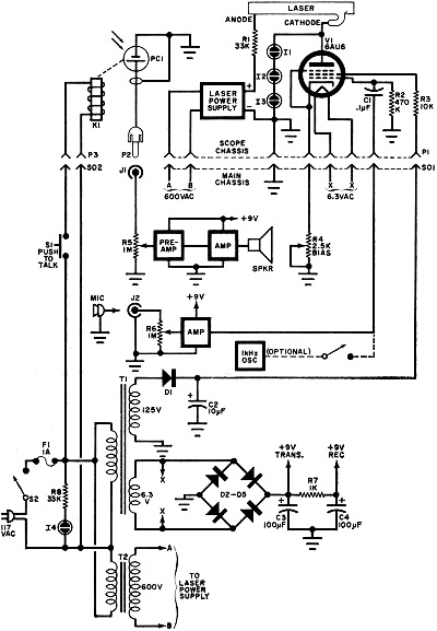
Fig. 6 - Complete telescope communicator showing the use of semiconductor audio amplifiers. Any neon lamps may be used for I1, I2, or I3 if their breakdown totals up to about 600 volts. The main chassis for the telescope communicator mounts the relatively heavy power supplies (except for the laser). all controls, and is connected to the telescope electronics via a multi-lead flexible cable. Microphone plugs into the rear. On the solar cell called for in the Parts List of Fig. 4, the black side is the sensitive area. Cement the shiny side of the cell to the bus bar and then slide the cell and relay assembly into position. Make sure that the cell switches cleanly in and out of the beam path as the relay is operated. The two leads from the solar cell are taken out of the same slit and terminated on a two-lug terminal strip mounted near the relay. Mount the empty half of the two-piece electronic chassis on the telescope tube, just below the two laser mounting rings, drilling mating holes in both chassis and telescope tube. Use short mounting hardware so as not to interfere with the beam path. Recheck all mechanical work and tighten the telescope tripod screws. To keep weight to a minimum, only the modulator pentode and the laser power supply are mounted in the chassis on the telescope. This is necessary to reduce the possibility of oscillation in the circuits. Mount the power supply on the inside of the chassis, using an insulated spacer (about 1/4") at each corner. Be sure that the high-voltage end is far enough from the metal to avoid arcing. The seven-pin tube socket for the pentode is mounted at one end, while a multi-lug terminal strip supports the ends of the wiring. A 1/2" grometted hole should be provided for the incoming cable. The circuit for the scope-mounted electronics is shown in Fig. 7. Only the relay, solar cell, and laser are external to the chassis. The circuit above SO1 is mounted at the scope. The lower portion is built in a larger conventional chassis.
View looking into end of telescope shows how the solar cell, in transmit condition, is out of beam path from laser to diagonal. In the receive mode, the cell enters the beam path between diagonal and eyepiece. Make sure that sensitive side of solar cell faces the diagonal.
In the simple transceiver, the solar cell is mounted within a tube having a dark interior - in this case, it's a clean Polaroid print coater. Cell is affected by ambient light so that it must be shielded during use. Any method of mechanical mounting may be used to position the cell correctly. When all electronic work is finished, attach the second half of the chassis to the one on the telescope. The cable should be placed where it will not interfere with scope operation. Fully open the ring mount thumb-screws and slide the laser into position as described above. Tighten the thumb-screws gently to avoid damaging the tube. Attach the plus side of the high-voltage supply to the laser anode and the negative side to the cathode. Make up a phono connector to connect the solar cell leads to J1. Connect the two leads to the relay. A small 90° prism is cemented to a plastic block to aim the laser light at the telescope eyepiece. The plastic block is press fit to the laser end. The transmit-receive relay is mounted to the telescope tube with the solar cell and rod passed inside through a hole cut in the telescope tube wall. Setup. Connect the far end of the multi-lead cable to the main chassis, along with the solar cell and microphone connectors. (You can substitute a radio for the microphone for testing.) The push-to-talk button may be temporarily shorted to keep the solar cell out of the beam path during the following optical alignment. Three commercial IC audio kits were used for all stages except the pentode modulator. Power supplies are mounted under the chassis. Telescope cable termination is on rear apron. It is assumed that the telescope optics have been set up as described in the telescope operating manual. On the main chassis, set bias control R4, volume control R5, and modulation control R6 to minimum resistance. Plug in the 117-volt line cord and turn on the power. The laser tube will blink a few times until V1 warms up. After the laser starts to glow at full power, allow the entire system to stabilize for a few moments. Adjusting the bias control should cause the laser glow to diminish a little. Set this control for maximum laser brilliance. Place the 90° plastic prism over the protuberance at the laser exit hole and adjust the prism so that the laser beam is reflected down the telescope eyepiece. Aim the telescope at a wall and keep adjusting the prism - and if necessary the position of the laser - until a red circle, with the diagonal mirror shadow centered in it, is clearly visible on the wall. At this point, the laser has been properly set up and should not be moved. If you have to keep looking at the laser beam, a pair of blue sunglasses may be worn to reduce the red glare. To test the system, aim the telescope at a distant mirror and reflect the beam back to a duplicate solar cell that has been connected to the main chassis. You can also use the second telescope of the communications system if you have built it at this time. With the light beam shining on the solar cell, make sure that the radio is playing at a reasonable volume and turn up the laser volume control R5. If artificial light falls on the solar cell, a hum will be heard; so for best reception keep the ambient light dim. Slowly adjust the bias control (R4) until the laser dims a little. Then bring up slightly the modulation control (R6) until music is heard from the main chassis speaker. Since R4 and R6 are interlocking in their action, you will have to adjust them together to get the desired results. If R4 is set for too low a beam level and R6 is set too high, modulation peaks may extinguish the laser. The automatic power supply will retrigger the laser, but the controls should be adjusted to prevent the drop-out. Once clean modulation has been obtained, the radio can be replaced by the microphone and R6 adjusted for this type of input.
Posted December 14, 2022 |
|||||||||||||
 |
|||||||||||||
|
|||||||||||||


|
||||||||||||||||||||||||||||||||||||


