|
August 1955 Popular Electronics
 Table
of Contents Table
of Contents
Wax nostalgic about and learn from the history of early electronics. See articles
from
Popular Electronics,
published October 1954 - April 1985. All copyrights are hereby acknowledged.
|
Here is a very basic introduction
to schematic reading from the August 1955 edition of Popular Electronics.
To someone who has been exposed to schematics and mechanical drawings for five decades,
reading them is second nature. However, to the newcomer to electronics, it can be
a bit cryptic. It is the equivalent of handing someone who has never read sheet
music from Beethoven's 5th and asking him to make sense of it. Of course there
is a lot more to schematics than presented here, but you have to begin somewhere.
Lingo of the Schematic
By George Berry
Strictly for the beginner; the how and why of radio or electronic schematics
plus pictorial vs. wiring
 If you enjoy building and experimenting with
electronics, but still feel a bit shaky about wiring up circuits directly from the
schematic diagram, take heart. Pictorial diagrams are all right to start with, but
they are not as easy to follow as they look. But schematic diagrams are actually
much easier to understand than they would seem to be. Most of them are a lot simpler
than, say, a road map, and easier to figure out than a diagram of an end-run play
in football. If you enjoy building and experimenting with
electronics, but still feel a bit shaky about wiring up circuits directly from the
schematic diagram, take heart. Pictorial diagrams are all right to start with, but
they are not as easy to follow as they look. But schematic diagrams are actually
much easier to understand than they would seem to be. Most of them are a lot simpler
than, say, a road map, and easier to figure out than a diagram of an end-run play
in football.
Let's assume you already recognize the standard symbols for the common parts
- tube, capacitor, resistor, and coil ... battery, headphones, antenna, and ground.
Once you have some idea of what these different gadgets do, it's almost impossible
to mistake what the symbols mean. They were designed that way.

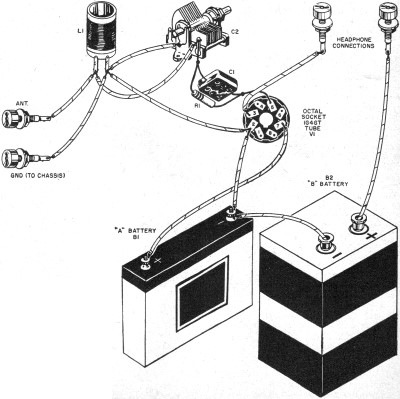
Fig. 1 (above). A wiring schematic contains the identical information conveyed
in the pictorial schematic in Fig. 2 (below). Beginners tend to favor the use
of the pictorial; but once familiar with the essentials behind the true wiring schematic,
it becomes obvious that the latter will always be best.

Beginners tend to favor the use of the pictorial.
The idea of the schematic diagram is simply to show what is connected to what,
in the simplest, most direct manner possible. You can take a schematic and compile
from it a list of what connections to make. Then you can follow that list with a
soldering iron and pliers and the circuit will be all wired up. Experienced people,
including engineers, usually do this mentally while they are working.
Let's take an example, say, the simplest possible one-tube radio receiver. This
set will work, incidentally, but don't build it except for practice. A very few
more parts would make a vastly better set, but that would spoil the neat simplicity
of our example. The schematic is shown in Fig. 1. Now let's proceed through
the mental processes that go with wiring it up.
First, mount on a board those parts which ought to be screwed
down. That means the tube socket and the tuning capacitor. Let's use a big board
and set the batteries on it too, so that it can be carried around. There are few
sounds as discouraging as the "clunk" of a heavy B battery plunging to the floor,
accompanied by the ripping noise of taut wires pulling radio parts out by the roots.
The coil can be screwed down, too, if it has a bracket. Some screw terminals
or Fahnestock clips for the antenna, ground, and headphones need to be fastened
on as well. Now we are ready to wire. Starting at the left, we see that the antenna
terminal, one end of the coil, and one side of the tuning capacitor C2 should all
be con-nected together. Do so. Next, and rather naturally, the ground terminal,
the other end of the coil, and the other side of the tuning capacitor C2 all go
together. The frame side of C2 is always the ground side. Now note that the little
mica capacitor C1 and the resistor R1 are connected directly across each other.
Let's solder them to-gether, and then see where the combination goes ... one end
goes to pin No.5 on the tube socket while the other end goes to the tuning capacitor
- that side which is con-nected to the antenna.
Where do the other socket terminals go? Well, No.3 goes directly to one side
of the phones. While we are at it, let's take care of the other side of the phones.
A long wire goes to the positive side of the B battery; make it red for "+". Now
there are only two connections left on the socket. Pin No.2 goes to the negative
side of the A battery, so let's solder a wire there. It goes to a couple of other
places, too. In fact, it looks as if pin No.2, the "A minus," the "B minus," and
ground are all connected together. Does it matter just what wires go where, so long
as these four places are all connected together? Well, it matters at v.h.f., but
not down here in the AM broadcast band. Let's do it in some reasonably direct way.
A wire from socket pin #2 should go to the frame (ground) side of the tuning capacitor.
It can be easily routed around via the terminal on L1. Color should be black for
ground, negative, and such things, if we are particular. As the B battery will be
sitting alongside the A battery, let's make the wire about six inches longer than
necessary. Skin the insulation six inches back from the end and connect that to
"A minus"; then skin the end and connect that to "B minus." It is simpler that way.
Now we ought to be finished ... except for pin No. 7. That goes to the plus side
of the A battery, and nowhere else. Better put a clip on the battery end of the
wire so we can turn off the unit.
Clip a wire from a water pipe or bed-spring or something onto the "ground" terminal,
drape ten feet of old magnet wire from a defunct auto speaker field over the window
frame for an antenna, connect the phones, and presto... Grandpa Jones, Peggy Lee,
news bulletins, and used-car commercials.
Why "A" and "B" Batteries
The terms "A" and "B" for batteries, for the benefit of those youngsters who
were not playing with radio in the 1920's, goes back to the time when all home radio
sets ran on batteries. Since "filament" and "plate supply" and such expressions
did not ring bells in the minds of the general public, the battery people came up
with some nice simple names having one letter each. When the family radio started
to get laryngitis, you opened up the top of the cabinet (they all had piano hinges)
and looked at the filaments. If they looked dim, you hauled the 6-volt storage battery
off the shelf under the table and took it out for a recharge. If this didn't fix
it, you had to run down to the corner radio store and exchange eight bucks for a
pair of 45-volt heavy-duty B batteries.
But suppose we end the history lesson and get back to diagrams. Figure 2 is a
pictorial diagram of the same circuit as Fig. 1. Now, honestly, do you still
think it's simpler than the schematic?
Actually, one big trouble with pictorials is that the man drawing the diagram
has less choice as to where he locates the parts. This makes for more of a tangle
in the wiring. Not too bad for simple circuits like this one, it gets rapidly worse
with two-and three-tube circuits, and the multiplicity of crossovers makes the wires
hard to follow without a flock of colored.
Wiring Schematic Preferred
A schematic, if it is drawn right, will have very few crossovers of leads. Then,
there are standard conventions that help, which are followed by almost everyone:
(1) stages are laid out in approximately a straight line, with the signal proceeding
from left to right; (2) auxiliary circuits go below the tube they affect, e.g.,
in a superhet the oscillator is drawn below the mixer; (3) power supply circuits
are drawn below, near the bottom of the sheet; (4) ground, filament, a.v.c., and
such low-voltage wiring is drawn along below the tubes, while high-potential or
"B plus" wiring may be drawn along above the tubes. It is hardly possible to follow
these conventions in a pictorial. Each pictorial is, hence, a one-shot affair so
far as learning goes. But every schematic understood, preferably redrawn, and perhaps
built, is a step toward a better understanding of electronics.
Posted August 26, 2020
(updated from original post on 8/23/2011)
|