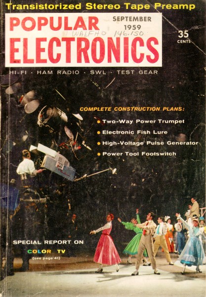
September 1959 Popular Electronics
 Table of Contents Table of Contents
Wax nostalgic about and learn from the history of early electronics. See articles
from
Popular Electronics,
published October 1954 - April 1985. All copyrights are hereby acknowledged.
|
The area code system was developed
by AT&T and Bell Laboratories in the 1940's, and went into effect in 1947. It
was called the
North American Numbering Plan (NANP) and included the United States
and Canada. States and provinces that had a single area code were assigned three
digit codes with 0 as the middle number. There were 86 area codes at that time.
States and provinces that had more than one area code distributed to them were given
three digit codes with 1 as the middle number. The first and third digits were allotted
according to population density in the city or region, with the most populated areas
getting the lowest numbers. When other countries adopted a similar system a
single number prefix, designated the World Zone, was added to the area codes.
Since North America was the first to implement the area code system, it received
the number 1. That is why North America phone numbers are of the form 1-[3-digit
area code]-[7-digit phone number]. -- Excerpted from
area-codes.com
The Magic of Cross-Country Communications
Here's how telephone calls and TV programs are sent from coast to coast
By Art Zuckerman
 If you've been reading your mail lately, you
may recall a letter from your local telephone company. This letter was about the
new system of direct long-distance dialing which makes it possible for you to call
Aunt Minnie in Minneapolis' just "by dialing 612, the area code number, plus her
phone number. If you've been reading your mail lately, you
may recall a letter from your local telephone company. This letter was about the
new system of direct long-distance dialing which makes it possible for you to call
Aunt Minnie in Minneapolis' just "by dialing 612, the area code number, plus her
phone number.
Ingenious new switching circuits make such long-distance dialing possible. But
these fancy new techniques wouldn't be worth a nickel without a way of getting messages
across the country quickly and economically. At the present time, we have two efficient
carriers of the cross-country electronic mailbag. These are the coaxial cable and
the radio relay systems.
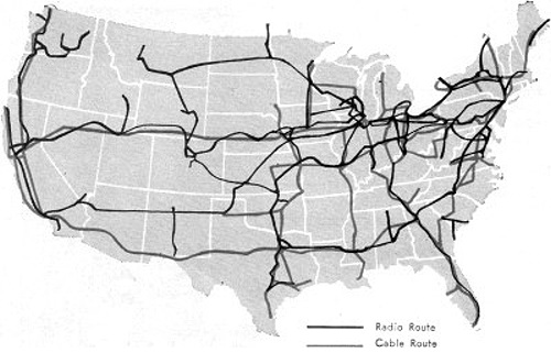
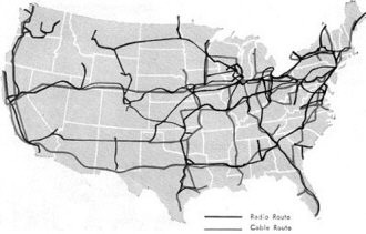
Some 16,000 miles of American real estate are covered by the radio relay towers
of the American Telephone & Telegraph Co., while another 10,000 miles hold AT&T's
buried coaxial cables.
Through Earth and Air. Although one sends its messages through
underground tubes and the other goes through the air, radio relay and coaxial
cable use the same basic techniques to handle thousands of telephone calls at the
same time. Network television programs are routed around the country on these same
carriers, right along with your phone call.
 Actually, a coaxial cable and a relay antenna
carry a broad band of frequencies. Some of the latest equipment covers eight times
the frequency span of the entire broadcast radio band. An individual telephone conversation
occupies only a narrow channel of the band, much as a single radio program represents
only a part of the total signal picked up by your receiving antenna. Actually, a coaxial cable and a relay antenna
carry a broad band of frequencies. Some of the latest equipment covers eight times
the frequency span of the entire broadcast radio band. An individual telephone conversation
occupies only a narrow channel of the band, much as a single radio program represents
only a part of the total signal picked up by your receiving antenna.
In the same way that your radio receives and separates many stations, so coaxial
cables and radio relay can carry an enormous composite signal and separate the many
individual voice channels at the receiving stations and cable terminals.
Why are there two systems? There are several reasons. First of all, the type
of terrain to be covered can determine whether coaxial cable or radio relay should
be used. In a mountainous area, radio relay is almost always called for, while coaxial
cable is favored in open country.
Another factor is local needs. Other things being equal, the system which best
suits local traffic requirements at a given time will receive the nod. At one point
in the game, radio relay may offer the greatest message-handling capacity; at another
time, cable equipment may forge ahead.
The costs of the two systems tend to average out. While radio relay is cheaper
to install, cable is cheaper to maintain and operate.
The two carriers of the cross-country electronic mailbag are the coaxial cable
and radio relay systems. Above is an inside view of a coax cable. At right is an
antenna tower at a radio relay station.
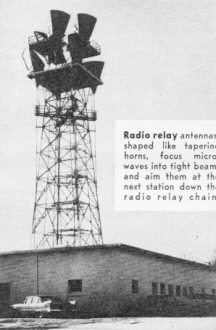 Radio relay antennas, shaped like tapering
horns, focus microwaves into tight beams and aim them at the next station down the
radio relay chain.

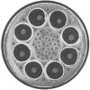 Coaxial cable is made up of eight coaxial
tubes plus a number of standarddwire conductors. Spacers made of polyethylene position
the center wires inside the hollow copper outer tubes.wire conductors. Spacers made of polyethylene position
the center wires inside the hollow copper outer tubes. Coaxial cable is made up of eight coaxial
tubes plus a number of standarddwire conductors. Spacers made of polyethylene position
the center wires inside the hollow copper outer tubes.wire conductors. Spacers made of polyethylene position
the center wires inside the hollow copper outer tubes.
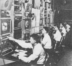
Television control terminals monitor programs coming in either on radio relay
or coaxial cable. One TV program ties up the equivalent of 600 telephone circuits.
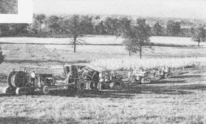
"Mickey Mouse" plow train can cut through most types of terrain, planting coaxial
cable and filling its trench as it goes along.
Each copper tube is roughly the diameter of a fountain pen. A copper wire runs
down the center of each tube, held in place by polyethylene insulating discs spaced
about an inch apart. Because the tube and the wire have the same axis, the tubes
are called "coaxial." This design offers unusually good shielding properties. It
prevents interference with other conductors. in the same cable and protects against
outside electrical disturbances.
For telephone purposes, the tubes are used in pairs - each transmitting in one
direction. When equipped with the latest design of related apparatus, some 1860
simultaneous conversations can be handled by each pair of coaxials.
Since signals carried by the cable weaken rapidly, a chain of booster amplifiers
spaced four to eight miles apart is necessary to refresh them. Depending on the
particular system, these repeater stations are mostly small, unattended units that
draw their power from the cable itself. A series of main stations supplies this
power and also provides overall maintenance.
Automatic Trouble-Shooters. The cable has an amazing ability
to look out for itself. Not so long ago, for instance, a farm hand in the South
was digging post holes when he hit something. The man was startled when the mysterious
object started hissing at him. He was almost as surprised when a Bell System maintenance
man showed up in short order.
The object our farm hand struck was, of course, a "coax." The hissing came from
gas - either nitrogen or. dehumidified air - escaping through a break in the casing.
The gas serves two purposes. First, by escaping under pressure, it keeps moisture
from entering the break. Second, it sets off an alarm at a main repeater station
and allows maintenance personnel to locate the damage from gauges that show the
point of lowest gas pressure.
Signal problems and power failure are other occasional sources of trouble in
the cables. Here, too, the coax has built-in safeguards. For example, only six of
the eight tubes are usually in operation. Two are kept in reserve for emergencies,
one set to handle signals in one direction and the other ready to transmit in the
opposite direction. If the commercial power should fail, batteries are automatically
cut in. Should these go out, emergency generators take over.
Different locations require somewhat different safeguards. In areas where the
soil offers a high resistance to electricity, a polyethylene insulating layer wards
off lightning damage. Where gophers are found, a wrapping of steel tape deprives
the critters of a tasty lead-sheath snack.
Radio Relay. Natural and man-made hazards are less of a problem
with radio relay. Since it operates in the microwave frequency range, it isn't affected
by static caused by lightning, nearby ignition systems, or even sunspots.
A radio relay chain is made up of a number of stations about 30 miles apart.
Each one must be within the line of sight of the station in front and behind, because
the microwaves they handle are highly directional and are focused into extremely
sharp beams. The relay stations are placed in a zigzag path rather than in a straight
line, so that there is no danger of a station's overshooting its mark and being
picked up by the next station down the line.
Because it uses such tightly focused beams, microwave relay employs power very
sparingly. It takes less than a watt - about enough to light up a pocket flashlight
bulb - to span the gap between stations. The tight focusing arrangement also conserves
frequencies at a station that feeds two or more relay chains. The station can send
out the same frequency in different directions without danger of interference.
In regular practice, however, a relay station receives a transmission on one
frequency band and then converts it to another frequency for relaying to the next
site. Here, the transmission is again sent out on the original frequency, and the
alternation of frequencies continues right on down the line. This practice eliminates
the possibility of part of a station's transmission feeding back into its own receiving
antenna.
The amplifiers that give the relay stations their punch really pack a wallop.
They can take a weakened signal and send it on with a million fold gain in strength.
As with coaxial cable, the radio relay system contains a number of built-in safeguards.
It, too, has spare emergency channels for use in case of trouble. Storage batteries
and motor-driven generators are ready to supply emergency power. An alarm system
spells out any trouble on a coded diagram at the nearest control office.
Multi-Purpose "Highway." Television and telephone traffic are
carried together on both radio relay and coaxial cable. The average TV circuit ties
up the equivalent of 600 telephone circuits. But, unlike telephone, it only goes
one way, and thus uses only half the two-way circuits involved.
Interestingly enough, the television picture and the audio portion of the show
are normally carried on separate channels. This means that technicians in the control
centers must coordinate the two sections of the program at the end of the line.
Since the audio is carried on lower-priced lines, network television doesn't
offer too much for the hi-fi enthusiast. Bell Telephone can supply circuits with
a top audio frequency response of either 5000, 8000, or 15,000 cps. The higher the
response, the higher the price of the service. For this reason, though some TV circuits
are occasionally rigged for the higher frequencies, the networks generally content
themselves with a 5000-cycle audio cutoff. Regular telephone frequency response,
incidentally, ranges from about 300 to 3000 cycles.
Ground Work. A lot of planning goes into the construction of
either system. For radio relay, topographical maps are used to locate clear paths
between sites and to avoid reflective surfaces, such as flat land or lakes, that
might harm the signal. Portable transmitters, receivers, and antennas are spotted
for field tests of prospective sites. Borings and soil samples tell what kinds of
foundations are in order.
Cables are laid in open country by tractor-drawn plow trains. A 27-ton job, tagged
the "Mickey Mouse," is the most powerful type in use. This monster's hydraulically
controlled plowshare can cut through almost any kind of terrain, feeding cable into
the ground and filling in the trench as it moves ahead.
In cities, on the other hand, or under highways and railroads, the cable is generally
placed in a conduit or pipe. Sometimes it must be run over bridges. Or, at river
crossings where there are no bridges, the cable may be laid by barges and dredges
using high-pressure water jets to trench it in the stream bed.
Aside from consideration of local problems, the telephone companies think it
is just plain good sense to use both radio relay and coaxial cable, instead of putting
all their eggs in one basket, since a disaster that affects one system isn't likely
to harm the other. This way, there is a good chance that an alternate route will
always be available should something go wrong with the prime channel.
And if this belt-and-suspenders approach is important under everyday conditions,
from the viewpoint of national defense it could be a matter of life and death.
Posted July 29, 2022
(updated from original post on
5/18/2012)
|