|
April 1959 Popular Electronics
 Table
of Contents Table
of Contents
Wax nostalgic about and learn from the history of early electronics. See articles
from
Popular Electronics,
published October 1954 - April 1985. All copyrights are hereby acknowledged.
|
Power transformers have not
changed too much since this article was appeared in a 1959 issue of Popular
Electronics magazine. Efficiencies might be up a bit, and maybe sizes down,
but other than that, the equations and implementation methods are about the same.
True, you will not find a lot of new transformers with secondaries that sport vacuum
tube filament and plate voltages, but their equivalents for ±15, ±12, ±5, etc. are
out there. 60- Hz transformers are of course most common here in the U.S. (50 Hz
in Europe), and 400 Hz is a common frequency for military equipment (ships,
aircraft, tanks, etc.), but I was surprised to learn that 25-cycle (25 Hz)
power was at one time common near hydroelectric plants. Niagara Falls, in Buffalo,
New York, was one of the first to adopt 25 Hz, in part because of a belief
that the AC motors used in nearby industrial applications would be more reliable
at lower commutator frequencies. Here is an informative paper from IEEE entitled, "25-Hz at Niagara
Falls - end of an era on the Niagara Frontier." Other frequencies such as 8-1/3
Hz, 16-2/3 Hz, 25 Hz, 33-1/3 Hz, and 41-2/3 Hz were proposed. As you might expect,
a lot of politics and corporate battling played into the final decision.
How to Make Power Transformer Substitutions
 By Eugene Richardson By Eugene Richardson
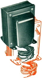
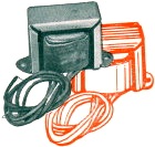
Power Transformers - those bulky heavy, and expensive items - are found in all
types of electronic equipment. Whatever your interest in electronics, you're sure
to have noticed one or more of these steel-clad components quietly humming to itself
off in a corner of the chassis. When a replacement is needed, or you're searching
for a particular item for a construction project, it's necessary to know the inside
story of the power transformers; how interchangeable are the units and what do the
specs mean?
The purpose of a power transformer is simply to convert the a.c. line voltage
into the higher and lower voltages required by electronic circuits. The two types
you'll come across are known as high-voltage plate and filament transformers. In
receivers and amplifiers you'll find the functions of both combined in a single
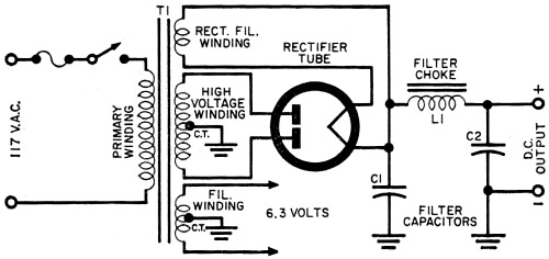
multiwinding general-purpose unit. A typical power sup-ply is in Fig. 1.
Size and Frequency. Physical size of a power transformer depends
upon both its power handling capacity and operating frequency. The higher the unit's
power rating, the larger the diameter of the wire needed in its windings and the
greater the amount of iron laminations in its core. A transformer designed to power
a one-tube audio preamplifier may measure a little over an inch on each side and
may weigh but a few ounces. However, the power transformer of a moderately large
television receiver will measure several inches on each side and be quite heavy.
The lower the frequency, the more iron is needed in the transformer core to maintain
operating efficiency. Hence, transformers designed for 25-cycle line operation are
larger and heavier than the more familiar 50-60 cps units. Since higher frequency
transformers require less iron, military equipment transformer frequencies may range
from 400 to 1000 cps.

Fig. 1 - Schematic wiring diagram of a typical power supply.

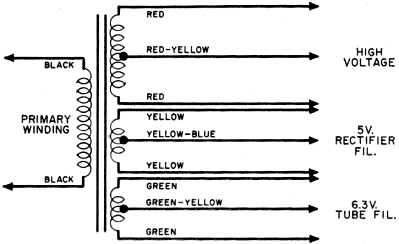
Fig. 2 - Standard color coding for power transformer leads.
Unless you live in an area supplied with 25-cycle power (a common frequency of
hydroelectric power plants), the chances are you use 60-cycle transformers in all
your projects. However, 400-cycle (or other high frequency) transformers are encountered
on the surplus market. As a general rule, a transformer will overheat, and may burn
out, if used at frequencies appreciably lower than those for which it was designed.
Thus, a 60-cycle transformer may overheat if connected to a 25-cycle line, as will
a 400-cycle transformer connected to a 60-cycle source.
Specifications. Aside from operating frequency, a power transformer's
electrical specifications are given in terms of primary voltage, secondary voltages
and rated currents. In some cases, the unit's power-handling capacity may be indicated
in watts or volt-amperes (va = primary voltage multiplied by current in amperes).
 A typical filament transformer may have the
following specifications: Primary, 105 - 120 volts, 60 cycles; Secondary, 6.3 volts,
CT, 2 amps. Such a transformer is designed for operation on a standard 60-cycle
power line. Although line voltage is nominally 115 volts, it may vary from 105 to
120 volts, depending on local conditions. A typical filament transformer may have the
following specifications: Primary, 105 - 120 volts, 60 cycles; Secondary, 6.3 volts,
CT, 2 amps. Such a transformer is designed for operation on a standard 60-cycle
power line. Although line voltage is nominally 115 volts, it may vary from 105 to
120 volts, depending on local conditions.
This unit's center-tapped (CT) secondary winding has a nominal rating of 6.3
volts, and is capable of delivering a current of 2 amperes without overload. The
exact secondary voltage will vary with the applied primary winding voltage and the
secondary load. If overloaded, the transformer will supply more than 2 amperes,
but the voltage will be low and the unit may overheat. Conversely, if less than
2 amperes are drawn, the secondary voltage may be somewhat higher than 6.3 volts.
Frequently, the presence of a center tap is indicated in the secondary voltage
specification rather than the abbreviation of "CT". For example, a transformer might
carry the following specs: Primary, 105-120 volts, 60 cycles; Secondary, 350-0-350
volts, 50 ma. This transformer has a standard primary winding and a secondary winding
delivering 350 volts on each side of its center tap; rated secondary current is
50 milliamperes. The secondary winding could also be described as 700 volts-CT,
50 ma.
Where a multi-winding power trans-former is used, such as in Fig. 1, the
voltage and current rating of each secondary winding are listed separately. A typical
set of specs reads as follows: Primary, 105-120 volts, 60 cycles; Secondary No.1,
300-0-300 volts, 50 ma.; Secondary No.2, 5.0 volts, 2 amps; Secondary No.3, 6.3
volts, CT, 3 amps.
Lead Identification. Connections to transformers are made to
fixed terminal lugs or to wire leads. If you purchase a new transformer, you'll
find that lead connection instructions are printed on the box, on a label on the
transformer, or on a separate sheet. But if you have a transformer salvaged from
another project or taken from a piece of used equipment, these connections probably
will have to be determined anew.
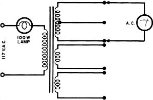
Fig. 3 - Basic test which you can make to identify power
transformer windings using an a.c. voltmeter.
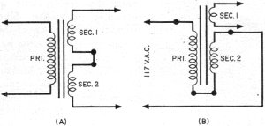
Fig. 4 - Two tricks to use in making emergency substitutions:
(A) two filament windings can be connected in series to supply higher voltages;
(B) a filament winding can be connected in series with the primary to lower all
secondary voltages.
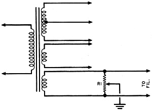
Fig. 5. How to obtain an "artificial" center tap on a filament
winding.
If the unit is of recent manufacture, and equipped with color-coded leads, you
can identify the leads by referring to the standard power transformer color code
given in Fig. 2. Filament center taps are not included in all transformers.
If the transformer is not equipped with color-coded leads, a simple technique
will indicate which is which. With the transformer disconnected, use an ohmmeter
to determine pairs of leads and center-tap connections. Check the resistance of
each winding. The winding having the highest resistance is usually the high-voltage
secondary and may read from 25 to several hundred ohms. The winding having a medium
resistance - generally from 5 to 25 ohms - is the primary. Finally, the lowest resistance
windings, usually less than I ohm, are the filament windings.
Having made a tentative identification, connect a standard 100-watt lamp in series
with the leads chosen as the primary leads and a source of line voltage as in Fig. 3.
The lamp should light, but not at normal brilliance. If it lights to normal brightness,
either the transformer is shorted (and should be discarded) or you've made an error
in choosing the primary leads.
Next, using an a.c. voltmeter, check the voltage across each winding, including
the primary. The ratios of these voltages will help you to identify the windings.
As a final step, remove the series lamp, applying full line voltage to the transformer
primary. Use your a.c. voltmeter to check the unit's output voltages and to identify
each winding positively. Remember that the voltage will read slightly higher than
normal because of the absence of a load.
Making Substitutions. A substitute power transformer should
be used only if the specified component is unobtainable.
When choosing a substitute, make sure that its secondary voltage specifications
are the same and that its current ratings equal or exceed those of the original.
For example, a transformer with a 250-0-250 volt, 60-ma. secondary may be used
as a satisfactory replacement for a unit rated at 250-0-250 volts, 40 ma. Similarly,
a filament transformer rated at 6.3 volts, 3 amperes, is a satisfactory substitute,
electrically, for a unit rated at 6.3 volts, 1.5 amperes.
A 5% difference in secondary voltage ratings will usually not affect circuit
operation. Thus, if a project calls for a transformer rated at, say, 360-0-360 volts,
substitutes with ratings of either 375-0-375 or 350-0-350 generally will be satisfactory.
Where a special transformer having several secondary windings is required, and
an exact duplicate is unobtainable, separate transformers can be used in place of
the single multi-winding unit, provided that adequate mounting space is available.
The transformer's 117-volt primary windings are connected in parallel.
 If special filament or bias voltages are required,
two (or more) windings can be connected in series to supply the necessary voltages,
as shown in Fig. 4(A). Connect adjacent winding leads together temporarily
and check the output voltage obtained between the "free" leads, using your a.c.
Voltmeter. If the output voltage is less than expected, the windings may be "bucking."
In this case, interchange the connections to one winding. If special filament or bias voltages are required,
two (or more) windings can be connected in series to supply the necessary voltages,
as shown in Fig. 4(A). Connect adjacent winding leads together temporarily
and check the output voltage obtained between the "free" leads, using your a.c.
Voltmeter. If the output voltage is less than expected, the windings may be "bucking."
In this case, interchange the connections to one winding.
It may be necessary to reduce the circuit's B+ voltage after installing a substitute
transformer. There are several ways of doing this. A small resistor (5 to 25 ohms,
10 watts) can be connected in series with one of the primary leads, or the effective
turns ratio of the transformers can be reduced by connecting one of the filament
windings in series with the primary, as shown in Fig. 4(B). The preferred methods
would be to substitute a rectifier tube with a larger internal voltage drop or lower
the value of the input filter capacitor (C1 in Fig. 1). If the hum level in
the d.c. output goes up; raise C2's value.
Often, a center-tapped filament winding may be needed, but may not be available
on the substitute transformer. In such a case, an electrical "center-tap" can be
obtained by connecting a 50-to-100-ohm adjustable wire-wound resistor across the
filament winding, as shown in Fig. 5. The adjustable tap is centered on the
resistor.
It is not necessary to use all the windings available on a multi-winding power
transformer. For example, suppose you need a general-purpose power transformer,
and find one with secondary specifications which match those of the needed unit
but with an "extra" 6.3-volt filament winding. Simply ignore the extra winding,
taping its leads to one side (taking care that they do not short together).
Mechanical specifications are important only when the substitute unit is used
as a servicing replacement or in the construction of equipment where the component's
physical size and shape are important. These specifications include overall dimensions,
weight, and type of construction or mounting.
Posted November 9, 2022
(updated from original
post on 10/14/2011)
|