|
November 1969 Popular Electronics
 Table of Contents Table of Contents
Wax nostalgic about and learn from the history of early electronics. See articles
from
Popular Electronics,
published October 1954 - April 1985. All copyrights are hereby acknowledged.
|
This "Microwaves for
the Beginner" article from a 1969 issue of Popular Electronics magazine
is still a good primer on how to build circuit boards which operate in the
gigahertz frequency realm - in this case 2,300 to 2,450 MHz, which falls
within today's popular 2.4-2.5 GHz ISM band. Grain-of-salt size components were
not available back then, so some techniques common in the day are used to
fabricate small value inductors and capacitors needed for efficient operation.
The transistor used is a KMC part number H104. I had a really difficult time
discovering who KMC was, but finally found a reference to them in a
patent and in a
CAGE Code list used by the U.S. government. KMC Semiconductor Corporation
was located in Long Valley, New Jersey. A couple instances of the KMC H104
transistor show up in "73" magazine, and interestingly, in one circuit it is
drawn as a PNP rather than an NPN. The antennas for both the transmitter and
receiver are dipoles mounted against a plated PCB ground plane.
Microwaves for the Beginner
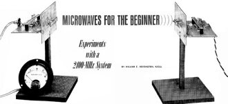 By William F. Hoisington, K1CLL By William F. Hoisington, K1CLL
As an electronics hobbyist or ham operator, you have probably built or experimented
with receivers and transmitters in all of the usual frequency ranges-up to the top
of the 450-MHz ham band. Isn't it about time you tried microwaves? In the past,
this has been difficult - special vacuum tubes or solid state devices that operate
in the microwave region were expensive and some of the metal-working (plumbing)
required was difficult.
The microwave system described here - including transmitter, antenna, and receiver
- can be built at a moderate cost, with a small amount of hardware work. It operates
in the S band from 2300 to 2450 MHz; and although the transmitting power and range
are very low, building and experimenting with this system will give you a good insight
into how microwaves are generated, propagated, and detected. In principle, the system
behaves just like its big brothers in telephone and TV distribution.
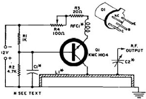
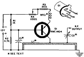
Fig. 1 - The transmitter uses a special microwave transistor
as a very low-power oscillator.
Parts List Transmitter
C1, C2 - See text
L1 - See text
Q1- KMC H104 high-frequency
transistor*
R1 - 1000-ohm, 1/2-walt resistor
R2 - 4700-ohm, '1/2-watt resistor
R3 - 20-ohm, 1/2-watt resistor
R4 - 100-ohm potentiometer
RFC1- Five
turns of #30 DSC wire, on 1/16" diameter
Misc. - 4-1/2" x 3" conventional copper-clad
PC board (2), thin brass sheet for C1 and C2, nylon screws and nuts (available at
hobby shops), thin copper strip for L1 and antenna, metal hardware, solder, etc.
* An H104 transistor is available from Rayville Associates, Mr.
S. Nelson, Parker Rd., RD 2, Lang Valley. N.J. 01853, for $5.
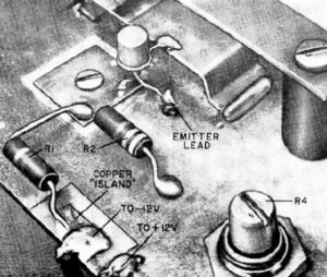
Fig. 2 - The emitter of Q1 couples to RFC1 via an insulated wire
fed through a hole in the PC board. Use a sharp blade to create an insulated "island"
for the -12-volt feed. Don't forget the mica insulator underneath bypass capacitor
C1.

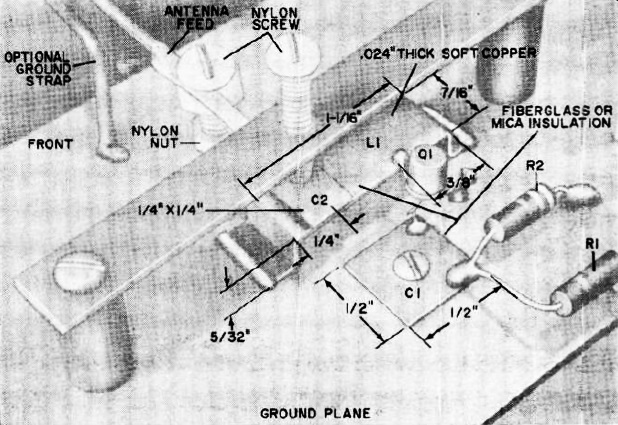
Fig. 3 - Mechanical construction of the transmitter. Antenna
coupling capacitor C2 has its thin lead wedged between the nylon support screw head
and a nylon nut. Use a piece of scrap PC board to make the tuning screw support
bridge, using a metal screw to tap the C2 hole.
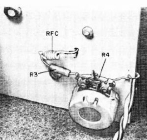
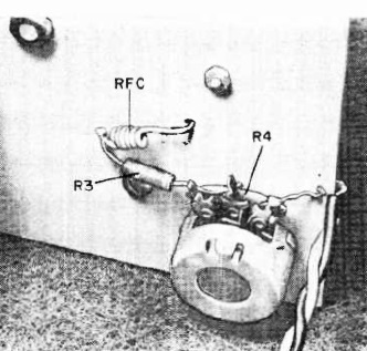
Fig. 4 - Underside view of the transmitter showing the location
of the RFC and R3. One end of the RFC feeds through a hole and contacts Q1 emitter.
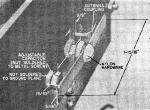
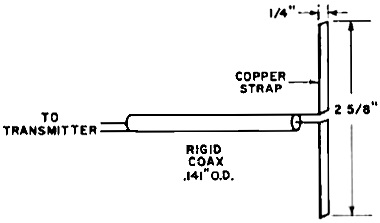
Fig. 5 - The antenna coupling (from C2 on the transmitter) is
1-15/16" made by creating a flat on one end of a piece of soft-copper bus bar. To
install it, rotate the antenna by 90-degrees. After installation, the antenna coupling
should be close, but not touching the antenna proper.
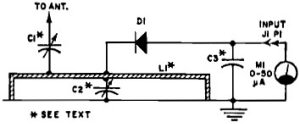
Fig. 6 - Because of the very high frequencies used, a special
microwave diode is used in the receiver. The diode can be inserted with either polarity
to L1, as long as it matches the polarity of meter M1.
Parts List Receiver
C1, C2, C3 - See text
D1 - PDO820 diode*
J1 - Phono
jack
L1 - See text
P1 - Coaxial phono plug
Misc. - 4-1/2" x 3" conventional
copper-clad PC board (2), thin brass sheet for C1, C2, and C3, nylon screws end
nuts (available at hobby shops), thin cooper strip for L1 and antenna, metal hardware.
solder, etc. PDO820 Schottky barrier diode is available front Parametric Industries,
Inc., 742 Main St., Winchester, Mass., 01890 for $2.75.
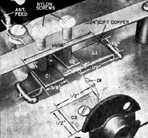
Fig. 7 - Construction details of receiver. Strapline Ll is the
same as used in the transmitter. Be sure to install mica insulators under capacitors
C1, C2, and C3. Receiver uses the same antenna construction as that used with the
transmitter.
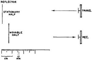
Fig. 8 - Basic interferometer is used to measure frequency. As
the movable half of the reflector is brought closer to the antennas, a series of
"nulls" will be seen on the receiver meter. You measure the distance between nulls
to determine frequency.
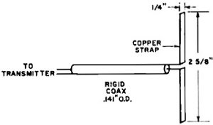
Fig. 9 - This simple dipole can be used to perform experiments
with various antenna arrays. These can include beams, horns, or parabolic systems.
Remove the old antenna and ground plane and install this.
In most microwave work, it is customary to use a technique known as "stripline"
in constructing the tuned circuit. Stripline consists of a lamination of a copper
ground plane, a layer of insulation, and then a thin strip of copper to conduct
the r.f. energy. Unfortunately, making stripline requires a precision layout and
chemical etching, and it is not easy to tune. The construction technique used in
this project results in a tuned circuit that is electrically the same as stripline
but it is easier to build and tune. In this case, we use a ground plane, air and
nylon for insulation, and ordinary thin copper strips for the r.f. conductors.
Transmitter
How It Works Transmitter
In the tuned circuit, the r.f. is bypassed by capacitor Cl and
bias is determined by the network of RI and R2. The base of QI is 180° out of phase
with the oscillator collector r.f. voltage. This is the necessary condition for
oscillation. The emitter of Q1 is r.f. decoupled from the power supply by RFC/ and
the transistor current is determined by the setting of potentiometer R4. There is
an internal in -phase feedback from collector to emitter. The tuned circuit. L1,
is a half -wave line grounded at both ends. At one instant, the center of LI (collector
connection) goes r.f. positive, while the base and the ground plane are negative.
One half -cycle later, the polarities of both points are reversed. If the Q (figure
of merit of LI and the circuit as a whole is sufficiently high, the circuit will
oscillate at a frequency determined by the physical dimensions and distance from
the ground plane of LI. The amateur band of 2300 to 2450 MHz has been picked for
this experimental microwave oscillator because that region is approved for experimental
amateur purposes. Changing the dimensions of L1 and its proximity to the ground
plane permits tuning the transmitter to any frequency within the band. Increasing
the emitter current by varying R4 increases the transmitter output power. Resistor
R3 is a safety resistor which prevents Ql from burning up from too much current.
Trimmer capacitor C2 couples the r.f. output to the antenna.
The schematic of the transmitter is shown in Fig. 1, while Figs. 2, 3, and 4
show the method of construction. The ground plane is a piece of conventional copper-clad
PC board measuring about 4-½" x 3".
The tuned circuit, L1, is made from a piece of thin (about 0.024") copper 7/16"
wide x 1-9/16" long. Bend a 1/8" lip at each end, then make another bend 5/32" from
each lip. The 1/8" lips are used to solder the inductor to the ground plane, so
that the inductor is 1-1/16" long and stands 5/32" from the ground plane. Apply
heat to the lips and coat the bottoms with solder. Center the inductor on the copper
foil of the ground plane and tin the area under each lip. Then solder the inductor
to the copper foil. Pick one side of the ground plane to be the front and the other
side the rear.
Make up bypass capacitor C1 using a thin sheet of copper or brass 1/2" square.
Deburr the edges, and drill a small hole in the center to accommodate a small screw
- either metal or nylon. Drill a similar hole through the ground plane at approximately
the center of L1 and about 1/3 of the way from the edge of L1 to the rear edge of
the ground plane. If you use a metal mounting screw, scrape away a small area of
copper around the ground plane hole so that the screw will not make electrical contact
with the ground plane.
Cut a piece of mica (a power transistor mounting insulator will do) or a small
piece of 3-mil fiberglass slightly larger than the plate of C1. Mount the capacitor
on the insulator and secure it in place with one edge of C1 parallel to the length
of L1. If you use metal mounting hardware, use an ohmmeter to make sure the capacitor
plate is not making contact with the ground plane.
Using Fig. 2 as a guide, drill a hole at the rear corner of the ground plane
large enough to accommodate the shaft of potentiometer R4. Scrape out an island
in the foil near the R4 shaft to form a terminal for the 12-volt connection, one
end of R1, and a lead to R4.
To make antenna coupling capacitor C2, cut a piece of thin brass so that it is
about 1 inch long and very narrow except for a 1/4" square tab at one end. This
is the capacitor plate. Glue a mica or fiberglass insulator sheet, slightly larger
than the capacitor plate, to the top of L1. centered about 1/4" from the end of
L1 (see Fig. 3). Drill a hole in the ground plane about half way between LI and
the front of the ground plane large enough to accommodate a nylon screw. Then following
Fig. 3, affix the thin end of the capacitor lead to this screw using a nylon nut
and making sure that the plate end of the capacitor fits directly over the insulator
on L1.
Using a piece of scrap plastic and standoff insulators, make a "bridge" over
L1 as shown in Fig. 3. Mark off a point directly over the plate of C2 and drill
a small hole in the bridge. Use a metal screw to tap the hole and insert a nylon
screw (having the same pitch) in the bridge so that it touches the capacitor plate
and can be used to adjust the spacing between the capacitor and L1.
Note where the collector of transistor Q1 is to be soldered to L1 as described
in the next paragraph. Directly under where the emitter lead will be, drill a small
hole to accommodate a length of insulated wire.
Using a heat sink on the transistor lead to protect the device from heat. solder
the collector lead to a point 3/8" from the end of L1 and the base lead to the metal
bypass capacitor C1. Bend the emitter lead toward the hole drilled in the preceding
paragraph. The fourth lead on the transistor is not used and can be cut off short.
Connect R1 and R2 into the circuit.
On the underside of the ground plane November, 1969 (see Fig. 4), connect one
end of R4 to the -12-volt terminal. Connect R3 to the other end and the rotor of
R4. Choke RFC1 is made by winding five turns of number 30 DSC wire around any 1/16"
form. You can impregnate it with coil dope or wax to make it retain its shape. One
end of RFC1 is fed through the hole in the ground plane and soldered to the transistor
emitter lead. The other end is soldered to R3.
Antenna
The ground plane for the antenna is the same physical size as that used for the
transmitter. To make the actual antenna (see Fig. 5) cut a piece of thin copper
sheet 1-15/16" X 5/16". Drill a hole in the center of the copper and in the center
of the ground plane so that the antenna can be mounted using nylon hardware.
The antenna is tuned by a small nut soldered to the end of a conventional 6-32
metal screw. Drill a hole in the ground plane 3/4" from the antenna mounting screw
hole and on the same center line. Solder a 6-32 nut to the copper foil of the ground
plane so that it is centered on the hole just drilled. Thread a 6-32 metal screw
an inch or so long into the nut from the back so that it protrudes to a maximum
on she antenna side. Put a metal nut on the screw so that the nut is flush with
the end of the screw. Solder the nut to the screw and file the end surface flat.
This screw is now a variable capacitor, with the flat end of the nut -screw combination
capable of being adjusted with respect to the antenna (when it is installed). On
the other side of the antenna mounting hole, about 3/8" away and still on the antenna
center line, drill a hole large enough for a piece of round copper bus bar. Trim
the copper foil away from the perimeter of the hole to avoid accidental grounding
when the antenna feed is installed.
Take a piece of soft-copper, round bus bar and, using a hammer, make a 1/4" x
1/4" flat on one end. This will be the antenna feed.
Solder a small L-bracket at each corner of the front of the transmitter ground
plane. Hold the antenna ground plane at right angles to the transmitter and adjust
the height so that the antenna feed hole is in line with the slim metal lead on
the antenna coupling capacitor (C2) secured in the nylon screw. Attach the antenna
ground plane to the L-bracket so that a continuous ground is made from the transmitter
ground plane to the antenna ground plane.
Once the two ground planes are fastened, pass the antenna feed bus bar through
its hole in the antenna ground plane so that the tab is approximately 15/32" from
the ground plane and bent out toward the end of the antenna. Be sure the feed line
does not touch the ground plane. Cut the other end of the bus bar so that it can
be soldered to the end of C2 in the transmitter. Rotate the antenna tuning capacitor
(on the antenna ground plane) so that the soldered-on nut is touching the nut on
the ground plane.
Slide, or thread, the actual antenna onto an inch -long nylon screw until it
touches the head of the screw and secure the antenna in place with a nylon nut.
Place another nylon nut on the screw and place the screw into its hole so that the
antenna is 15/32" off the ground plane (about 1/5 of a wavelength). Secure the antenna
in place with a metal (or nylon) nut at the rear of the board. Position the antenna
feed so that it is close to but not touching the antenna.
The antenna-transmitter combination can be mounted on a wood base. Connect a
wire to the -12-volt terminal "island" and another wire for the +12-volt connection
to the main foil of the transmitter ground plane.
Receiver
How It Works Receiver
The tuned circuit of the receiver is similar to that of the transmitter.
Trimmer capacitor Cl couples the antenna to the tuned circuit. The rest of the circuit
is a conventional crystal detector with a microammeter as the readout, Because of
the very high frequencies involved, a Schottky - barrier diode must be used. Unlike
conventional diodes, this device is especially made to operate efficiently at microwave
frequencies. Capacitor C3 is an r.f. bypass for the meter.
The schematic of the receiver is shown in Fig. 6. Inductor L1 and bypass capacitor
C3 are fabricated just as they are for the transmitter and are shown in Fig. 7.
The receiver has a tuning capacitor (C2) made up of a piece of thin brass sheet,
1/4" wide, bent so that a small lip can be soldered to the ground plane at the center
of L1. Another lip on the top straddles L1 but is separated from it by an insulator.
The antenna coupling capacitor C1 is similar to that in the transmitter. Nylon screws
for adjusting C1 and C2 are supported in the plastic bridge over L1.
Diode D1 is soldered to the center of L1 (either polarity) and to the bypass
capacitor. A phono jack with the shield pin soldered to the ground plane and the
center pin connected to the bypass capacitor serves as a meter connector. The antenna
for the receiver is constructed in the same manner as that for the transmitter.
A 50-microampere meter is used to measure the signal level of the rectified signal
output from D1. The meter can be connected through a length of twin - conductor
cable and a suitable plug and placed for easy viewing.
Operation
To tune the receiver to the transmitter, place the two units a short distance
apart on the workbench, with the antennas facing each other. Supply power to the
transmitter from a 12-volt d.c. source being careful to observe the correct polarity.
Set R4 between half and resistance. The receiver meter may or may not show an indication
of output. Gently adjust C2 on the receiver, looking for a meter indication. Tuning
may be sharp, so be careful. If the two units are close together in frequency, the
meter should show a signal somewhere in the course of tuning C2.
Once a signal is detected, adjust the transmitter antenna coupling capacitor
C2, the transmitter antenna tuning capacitor and potentiometer R4 for maximum signal.
With the transmitter rough tuned, adjust the receiver antenna coupling capacitor
C1 and the receiver antenna tuning capacitor for maximum signal. Once these have
all been adjusted for a maximum signal, trim the transmitter and receiver coupling
tabs for maximum signal and recheck all variable adjustments. As the received signal
strength increases, it may be necessary to separate the two devices by a couple
of feet more.
Frequency Measurement
Once the microwave system is operating, a frequency check must be made to make
sure that it is operating within the 2300-2450-MHz band. The approach (see Fig.
8) is called "interferometry" and was first used over a century ago to measure the
frequency of light waves. (Heinrich Hertz used it in 1887 to measure the first electromagnetic
waves ever generated.)
Place the transmitter and receiver side by side so that their antennas are facing
in the same direction. Place a ruler calibrated either in inches or centimeters
at 90 degrees to the plane of the antennas and about 2 feet in front of them. Make
two flat metal reflectors (several inches on a side) and place them in front of
the two antennas at the zero mark of the ruler. The butting edges of the two reflectors
should be approximately centered between the transmitter and receiver antennas.
Make one of the antennas fixed; leave the other movable. Turn on the power at the
transmitter and observe that the receiver readout indicates upscale. This proves
that r.f. energy radiates from the transmitter, hits, and is reflected back from,
the metal sheets, and produces a reading on the receiver.
Slowly slide the movable reflector toward the antennas. You will soon reach a
point where the received power drops to a null and then rises again. This is the
half-wave point where half of the transmitted r.f, is being supplied to the receiver
out of phase with the signal from the fixed reflector. Carefully note and record
the position of the movable reflector as indicated by the ruler. Keep sliding the
movable reflector in toward the antennas, recording the exact points where nulls
occur.
Calculate the centimeters or inches difference between each ruler indicated,
add them up and divide by the number of nulls measured. This will give the average
half wavelength. Double the value to obtain the full wavelength.
For the band being used here, full wavelength for 2300 MHz is 13.04 cm or 5.13
in.; and for 2450 MHz, 12.24 cm or 4.81 in. If your wavelength is not within these
limits, bend tuning inductor L1 to change the frequency. Retune the receiver to
the transmitter either with C2 (if the frequency difference is not too great) or
by bending 1.1 in the receiver.
Microwave Experiments
Once your microwave system is operating on frequency, you can experiment with
various types of antennas and reflectors. For instance, with the transmitter and
receiver facing each other a couple of feet apart, note that placing a metal sheet
above the transmission path will greatly boost the signal. This is similar to the
way the ionosphere reflects low-frequency r.f. signals.
Placing a pair of metal sheets near either antenna so that the antenna is at
the apex of a right angle also boosts the signal. This is a basic horn antenna.
It can be used at either the transmitter or the receiver, or both. The signal strength
can be vastly increased by various antenna configurations, even though the transmitter
power remains unchanged.
To demonstrate this further, make a dipole as shown in Fig. 9. Connect the center
feed to the thin coaxial cable to the transmitter antenna coupling capacitor C2
and the shield to the ground plane. Disconnect the regular antenna. Now you can
add directors and/or reflectors to the basic dipole to experiment with beam arrays.
A couple of things will become apparent as you experiment: First, as gain goes up,
directivity increases; second, to double the range (distance), you must have four
times the power. The latter can be proved by using the potentiometer on the transmitter
to vary the power. A milliammeter can be inserted in the 12- volt line to measure
the transistor current.
In experimenting with various horns and arrays, remember that, to get about 20
dB of gain, the antenna aperture should be at least six wavelengths square (or 36
square wavelengths) at the aperture.
The transmitter can be audio modulated by conventional techniques and such a
system makes a very interesting Science Fair project. Microwave signals can be "bounced"
around corners and over other intervening objects, by means of simple metal reflectors.
When a hand is placed in the beam path, the signal level changes, showing that the
microwave r.f. is actually carrying the signal.
Posted February 13, 2023
|